Electrically isolated power and data coupling system suitable for portable and other equipment

a power and data coupling system and portable technology, applied in the integration of power network operation systems, instruments, diagnostic recording/measuring, etc., can solve the problems of optimum design, high danger of electrocution of patients or medical staff, and use of exposed electrical contacts

Inactive Publication Date: 2005-03-22
DRAGERWERK AG
View PDF43 Cites 88 Cited by
  • Summary
  • Abstract
  • Description
  • Claims
  • Application Information

AI Technical Summary

Problems solved by technology

In some commercial devices, particularly medical equipment, the danger of electrocution of patient or medical staff is so great that additional steps are taken to ensure galvanic isolation and prevent electrical breakdown even in the presence of large voltages as high as 5 kV that may appear, for example, in defibrillators.
This technique has been used in rechargeable patient monitoring equipment, and in rechargeable toothbrushes and shavers where an alternative technique, such as the use of exposed electrical contacts, is particularly undesirable because of the moist environment causing corrosion, shorting and increased shock hazard.
Known barrier technique transformers continued the traditional practice of utilizing cores of approximately constant cross section although this is not the optimum design where the magnetic circuit includes a large air gap.
Known barrier technique transformer devices are typically relatively inefficient, well below the 80% level achievable in conventional DC-DC converters.
This wastes power and creates excess heat.
In addition, the power density of known barrier technique transformer devices is typically relatively low, restricting its use to low power devices such as toothbrushes and shavers (where recharging power may be 1 to 3 watts, for example), or alternatively such devices involve relatively large and heavy transformer magnetic components.
These disadvantages result from poor coupling between input and output windings.
However, there are locations in which continuous RF transmissions from the monitoring equipment may cause problems and must be carefully planned for.
This instrument causes an unpredictable amount of RF energy and could possibly interfere with the RF link of the monitoring equipment.

Method used


Image

  • Electrically isolated power and data coupling system suitable for portable and other equipment
  • Electrically isolated power and data coupling system suitable for portable and other equipment
  • Electrically isolated power and data coupling system suitable for portable and other equipment

Examples


Embodiment Construction

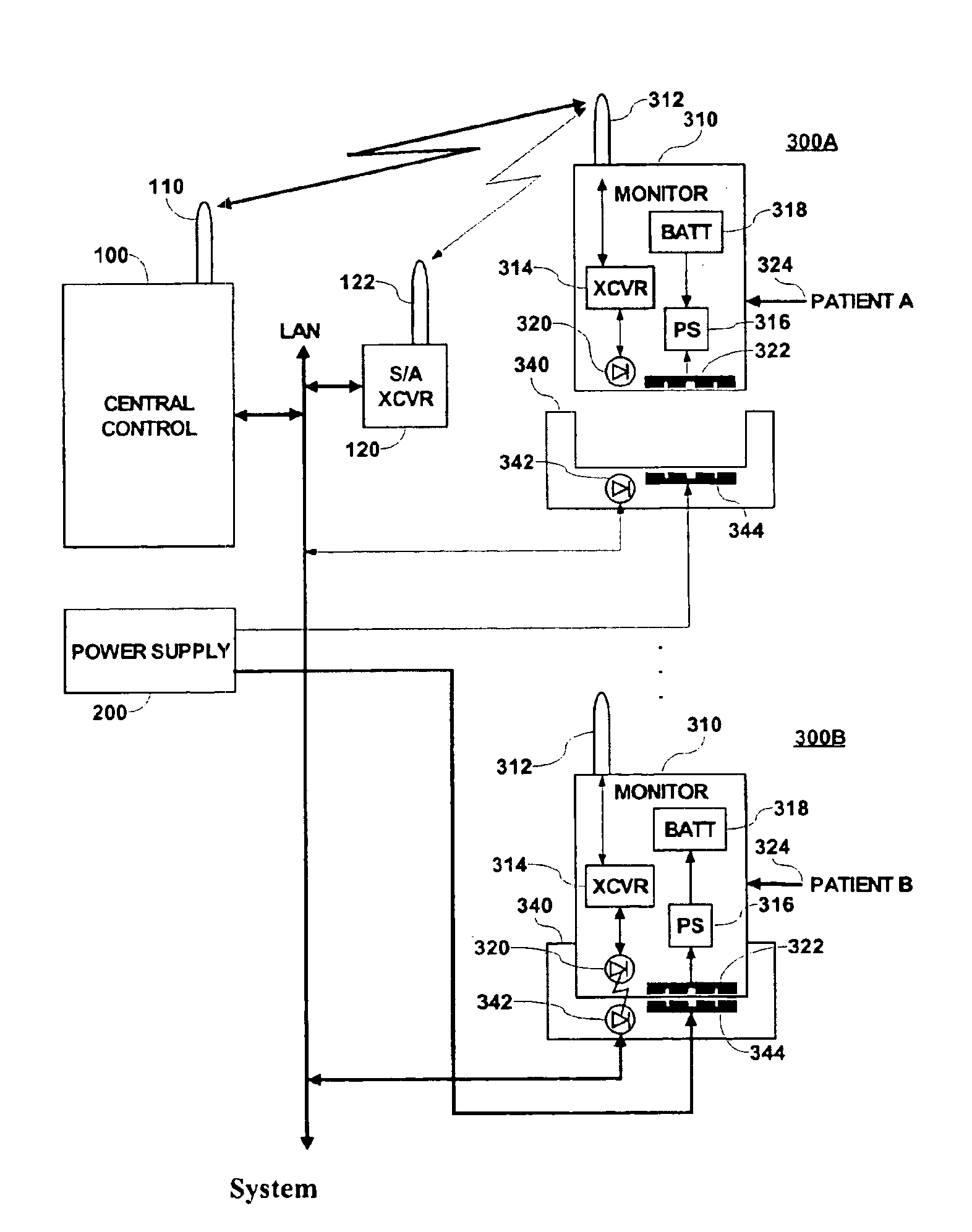
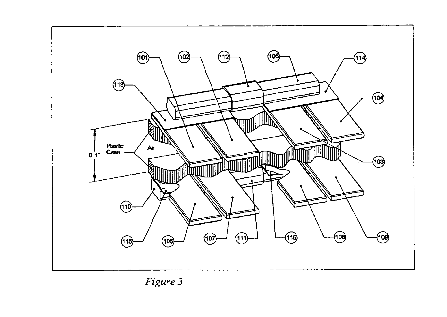
Known systems transmit power across an interface between two separable elements comprising a power source and a device to be powered using a magnetic assembly comprising a traditional transformer core with a uniform magnetic cross sectional area. This may comprise, for example, two “C” cores placed in close proximity to one another to make a C—C transformer where the two gaps in the two legs of the C—C transformer are located at the interface between power source and the powered device, or alternatively may comprise two halves of a traditional “pot” core assembly where the mating surfaces of the halves are located at the interface. In either example, the gaps at the interface would be occupied by a plastic or other material comprising the enclosure or case of the power source and powered device, hereinafter referred to as “case material”.

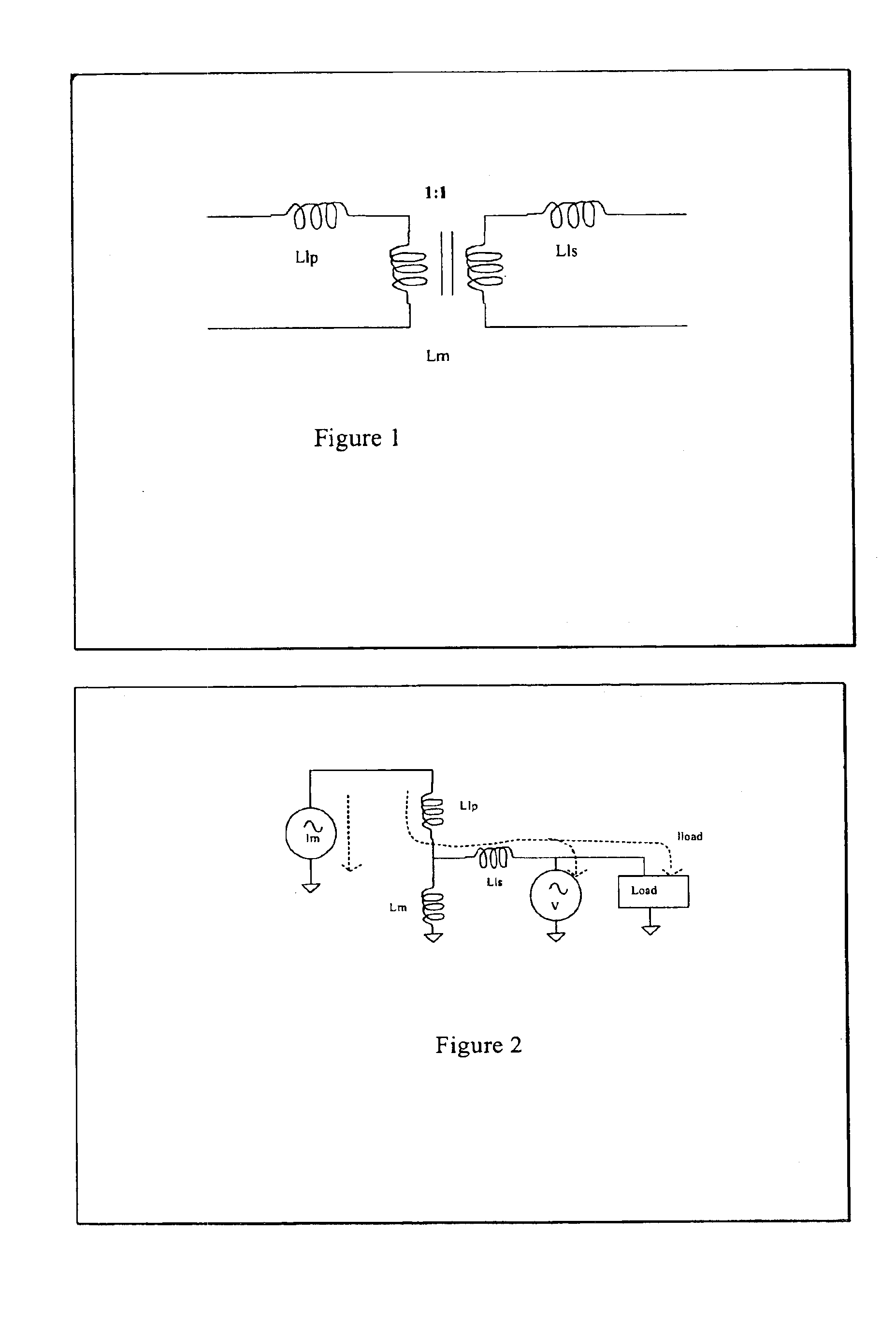
A major drawback of this approach is that a substantially constant magnetic cross sectional area of the cores results in a magnetic cross sectional...


PUM


Abstract

An electrically isolated combined power and signal coupler is usable for a portable medical monitoring device attachable to a patient in a medical environment. A power coupling system transfers power between a power source and a powered device separated by a physical and electrical isolation barrier. The system comprises a power coupler including in a first device, a first section of a magnetic circuit including a first core section of magnetically permeable material of cross-sectional area substantially larger at an isolation barrier interface than within a first winding located on the first core section. The first section of magnetic circuit being suitable, in a docking mode, for positioning adjacent to a second section of magnetic circuit in a second device to form a completed magnetic circuit used to transfer power between said first and second device. The second section of magnetic circuit including a second core section with a second winding magnetically coupling with the first winding via the completed magnetic circuit in the docking mode for the power transfer. The first core section comprises at least one substantially planar core section at the isolation barrier interface for positioning adjacent to a corresponding substantially planar core section of said second section of magnetic circuit at the isolation barrier interface to form the completed magnetic circuit without a device containing the second section of magnetic circuit enveloping a significant portion of the substantially planar core section.

Description

FIELD OF THE INVENTIONThe present invention relates to a power and signal coupler for a portable medical monitoring device designed to be connected to a patient in a medical environment.BACKGROUND OF THE INVENTIONElectrical transformers use inductive coupling of windings, in combination with a core of magnetic material, to transfer power from one circuit to another while maintaining galvanic isolation between the two circuits, in addition to increasing or decreasing output AC voltage levels. The galvanic isolation is needed to power devices that come into contact with people to provide safety and avoid electrocution. Typical transformers use insulating materials such as winding insulation or plastic bobbins between the windings and core to prevent them from touching and maintain galvanic isolation. In some commercial devices, particularly medical equipment, the danger of electrocution of patient or medical staff is so great that additional steps are taken to ensure galvanic isolatio...

Claims


Application Information

Patent Timeline
Patent Type & Authority Patents(United States)
IPC IPC(8): H02J7/00H02J13/00H02J7/02H04B1/38
CPCH02J7/0021H02J7/0027H02J7/025H02J13/0075H02J13/0096H02J13/0086Y04S20/221H04B1/3816H04B1/3883Y02B70/3216H02J2310/12H02J13/00004H02J13/00028Y02B70/30H02J13/00022H02J50/10H02J50/70
Inventor FITCH, JOHN KENNETHKELLY, CLIFFORD MARK
Owner DRAGERWERK AG
Why Eureka
Try Eureka