Apparatus for mounting an optical element in an optical system

Inactive Publication Date: 2005-03-22
CARL ZEISS SMT GMBH
View PDF18 Cites 48 Cited by
  • Summary
  • Abstract
  • Description
  • Claims
  • Application Information

AI Technical Summary

Benefits of technology

The present invention is therefore based on the object of creating an apparatus for mounting an optical element that, on the one hand, exerts few or small forces on the optical element, that is to say is very well decoupled in terms of

Problems solved by technology

The problem with a soft bearing consists, however, in th

Method used


Image

  • Apparatus for mounting an optical element in an optical system
  • Apparatus for mounting an optical element in an optical system
  • Apparatus for mounting an optical element in an optical system

Examples


Embodiment Construction

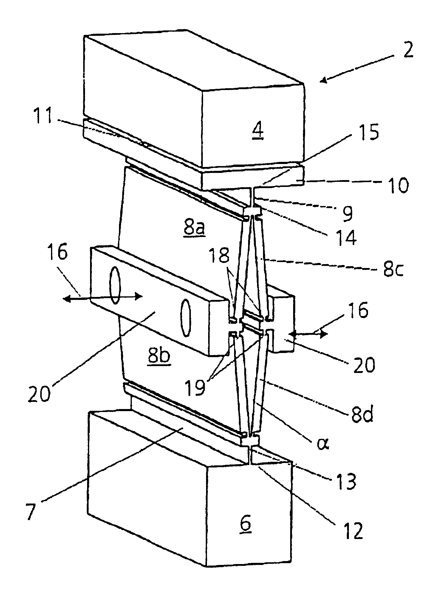
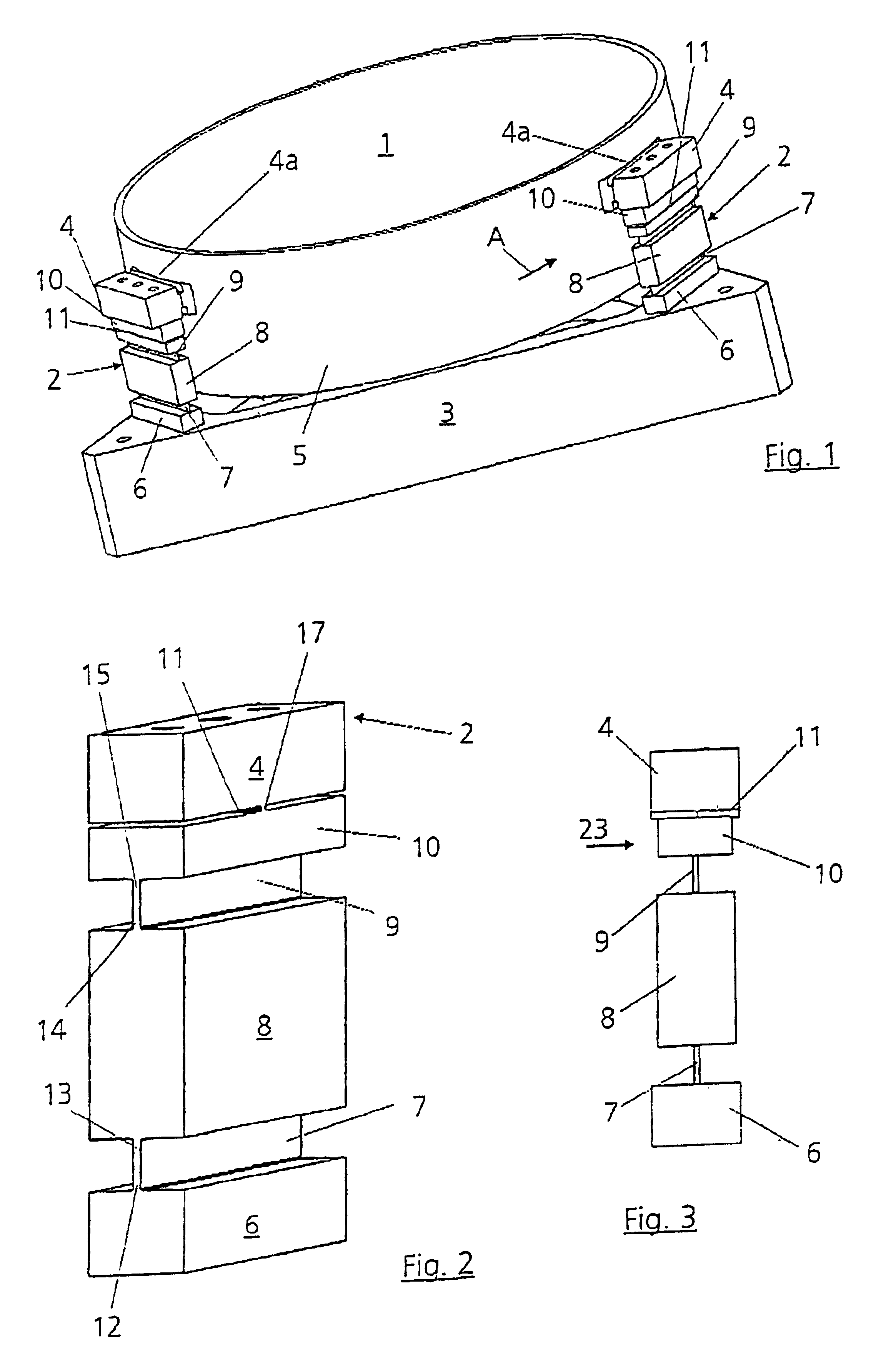
An optical element, for example a mirror 1, is connected to an external base structure 3 by three bearing devices 2 arranged uniformly distributed over the circumference. The base structure 3 can be part of an optical system, for example a projection lens in semiconductor lithography. The illustrated triangular shape of the base structure is to be recorded merely by way of example. If required, other shapes such as, for example, a circular one are possible here.

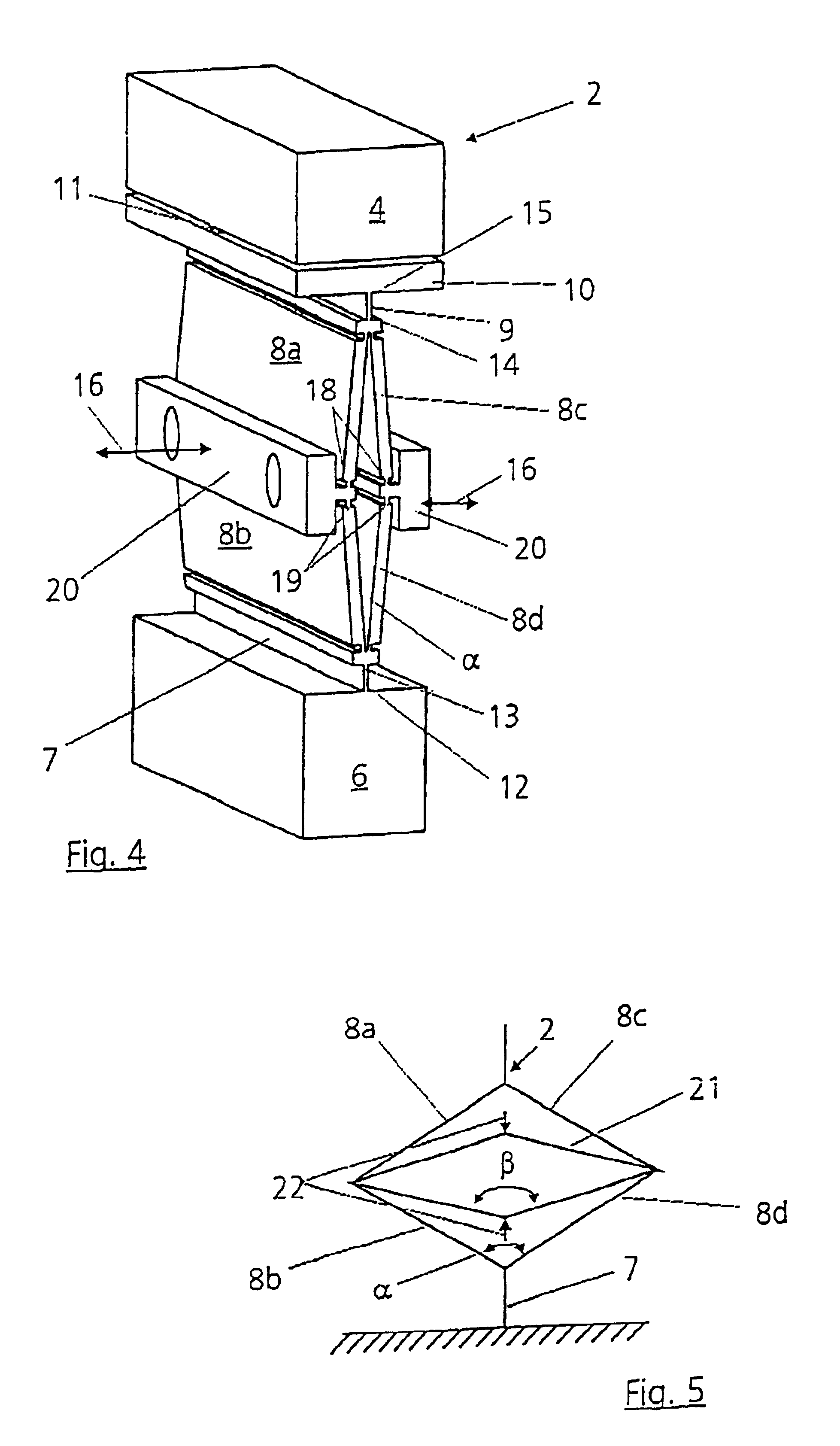
The bearing devices 2 are designed such that they are very strongly decoupled in terms of deformation and therefore do not pass disturbances acting from outside via the base structure 3 onto the optical element 1. The base structure is of very stiff design (preferably being ceramic), in order to decouple forces coming from outside as effectively as possible from the bearing elements and the mirror. A two-fold decoupling deformation is achieved in this way. A first embodiment of a bearing device 2 is illustrated in FIGS. 2 to ...


PUM


Abstract

An apparatus or mounting an optical element in an optical system, in particular a mirror or a lens, in a projection exposure machine, in particular a projection lens in semiconductor lithography, is connected to an external base structure with the aid of at least three articulation sites that are arranged on the circumference of the optical element and at which a bearing device acts in each case, wherein the bearing device has at least one bending element, resembling a leaf spring, arranged tangentially to the optical element, and at least one bending element, resembling a leaf spring, arranged in the radial direction relative to the optical element.

Description

RELATED APPLICATIONThis application relates to and claims priority to corresponding German Patent Application No. 101 15 914.5 filed on Mar. 30, 2001.BACKGROUND OF THE INVENTION1. Field of the InventionThe invention relates to an apparatus for mounting an optical element in an optical system.More specifically the invention relates to an apparatus for mounting a mirror or a lens in a projection objective of a projection exposure machine in semiconductor lithography.2. Description of the Related ArtOptical elements, such as mirror and lenses, in optics, in particular in semiconductor lithography, are to be mounted isostatically and therefore in a fashion decoupled in terms of deformation such that disturbances acting from outside as far as possible do not act on the optical element. It is known for this purpose to mount the optical element in an appropriately “soft” fashion. The problem with a soft bearing consists, however, in that sufficiently high natural frequencies are not reache...

Claims


Application Information

Patent Timeline
IPC IPC(8): G02B7/02G02B7/00G02B7/198G03F7/20H01L21/027
CPCG02B7/023
Inventor PETASCH, THOMASMUENKER, HARTMUTKLEIN, KLAUS-DIETER
Owner CARL ZEISS SMT GMBH
Why Eureka
Try Eureka