Organic laser having improved linearity

a laser and organic technology, applied in the field of organic lasers, can solve the problems of non-linear variation of laser light output, device with low carrier mobilities, undesirable properties,

Inactive Publication Date: 2005-03-22
EASTMAN KODAK CO
View PDF11 Cites 15 Cited by
  • Summary
  • Abstract
  • Description
  • Claims
  • Application Information

AI Technical Summary

Benefits of technology

e) a thermally conductive transparent layer disposed between the bottom dielectric stack and the organic active region or between the top dielectric stack and the organic active region or both.
A feature of the present invention is that by the use of properly positioned thermally conductive transparent layers in organic vertical cavity lasers, significant improvements can be made in the linear laser output response and in reducing the spectral linewidth broadening.

Problems solved by technology

A problem with all of these structures is that, in order to achieve lasing, it was necessary to excite the cavities by optical pumping using another laser source.
A main barrier to achieving electrically-pumped organic lasers is the small carrier mobility of organic material, which is typically on the order of 10−5 Cm2 / (V-s).
This low carrier mobility results in a number of problems.
Devices with low carrier mobilities are typically restricted to using thin layers in order to avoid large voltage drops and ohmic heating.
Unfortunately for actual organic-based VCSEL devices, as shown in FIG. 1, the laser light output varies non-linearly with pump-beam power density.
In addition to the saturation of the laser output power, organic VCSEL laser devices also show the undesirable property that the spectral width of the laser emission increases dramatically with pump-beam power density, as opposed to the ideal situation where the linewidth remains relatively invariant with pump-beam power density.

Method used


Image

  • Organic laser having improved linearity
  • Organic laser having improved linearity
  • Organic laser having improved linearity

Examples


example 1

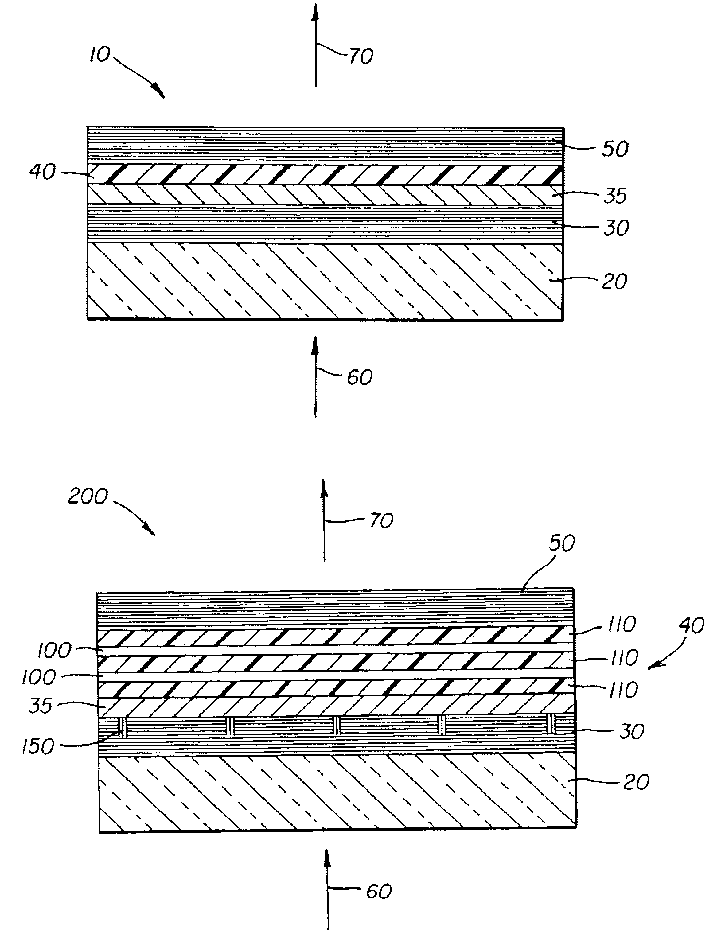
In order to determine the impact on the lasing characteristics of placing a thermally conductive layer adjacent to the organic active region 40, a laser device 10 was fabricated where the top dielectric stack 50 was replaced by a Ag mirror. The laser structure was deposited on a pre-cleaned 6-inch quartz substrate 20. Over the substrate 20 was deposited by conventional electron-beam deposition at 240° C. the bottom dielectric stack 30, which was composed of alternating high and low refractive index layers of TiO2 and SiO2, respectively. The resulting dielectric mirror had a measured peak reflectance of ˜99.3% at 560 nm. On top of the bottom dielectric stack 30 was deposited, by high vacuum thermal evaporation, the organic active region 40, where in order was grown 149 nm of TAPC, 30 nm of Alq with 0.5% C545T, and 207 nm of TAPC. Lastly, a 200 nm thick Ag metal mirror was deposited by high vacuum thermal evaporation.

Since the top dielectric stack 50 was replaced by a Ag mirror, both ...


PUM


Abstract

An organic vertical cavity laser device includes a substrate; a bottom dielectric stack reflective to light over a predetermined range of wavelengths and being disposed over the substrate, and an organic active region for producing laser light. The device also includes a top dielectric stack spaced from the bottom dielectric stack and reflective to light over a predetermined range of wavelengths, and a thermally conductive transparent layer disposed between the bottom dielectric stack and the organic active region or between the top dielectric stack and the organic active region or both.

Description

FIELD OF THE INVENTIONThe present invention relates to organic lasers which have improved linearity as a function of input power.BACKGROUND OF THE INVENTIONVertical cavity surface emitting lasers (VCSELs) based on inorganic semiconductors (e.g. AlGaAs) have been developed since the mid-80's (K. Kinoshita et al., IEEE J. Quant. Electron. QE-23, 882 [1987]). They have reached the point where AlGaAs-based VCSELs emitting at 850 nm are manufactured by a number of companies and have lifetimes beyond 100 years (K. D. Choquette et al., Proc. IEEE 85, 1730 [1997]). With the success of these near-infrared lasers, attention in recent years has turned to other inorganic material systems to produce VCSELs emitting in the visible wavelength range (C. Wilmsen et al., Vertical-Cavity Surface-Emitting Lasers, Cambridge University Press, Cambridge, 2001). There are many potential applications for visible lasers, such as, display, optical storage reading / writing, laser printing, and short-haul teleco...

Claims


Application Information

Patent Timeline
Patent Type & Authority Patents(United States)
IPC IPC(8): H01S3/091H01S3/14H01S5/30H01S5/42H01S3/16H01S3/08H01S5/00H01S5/183H01S5/04H01S5/36
CPCH01S5/36H01S5/041H01S5/18383H01S2301/173H01S5/423A62C3/16A62C13/76A62C31/02A62C31/28A62C37/14
Inventor KAHEN, KEITH B.LEBENS, JOHN A.
Owner EASTMAN KODAK CO
Why Eureka
Try Eureka