Optical cross-connect switch

Active Publication Date: 2005-03-22
FOR NAT RES INITIATIVES
View PDF2 Cites 12 Cited by
  • Summary
  • Abstract
  • Description
  • Claims
  • Application Information

AI Technical Summary

Benefits of technology

Thus, the beam shaper needs to have an amplitude transfer function G(x,y|x′,y′) that satisfies equations (1) and (3). All such transfer functions are too complex to be realized by using traditional optics. However, the inclusion of diffractive optical elements (DOEs) provides enough

Problems solved by technology

Their large size and mass give them a large moment of inertia, which limits their tilting speed to about 10 ms.
Moreover this problem becomes exacerbated as the number ports in the switch increases, because this implies a smaller angular separation between ports.
These kinds of structures are difficult to fabricate with currently well-established micromachining techniques.
However this approach significantly complicates the device.
Furthermore, making large diameter mirrors that are stiff and optically flat is difficult.(4) Actuation: Arrays of tilt-mirrors are typically actuated electrostatically.
However this type of actuation has a possible collapse instability (“snap-down”), which arises because the electrostatic force varies as the inverse square of the electrode separation, whereas the mechanical restoring force typically increa

Method used


Image

  • Optical cross-connect switch
  • Optical cross-connect switch
  • Optical cross-connect switch

Examples


an embodiment 111c

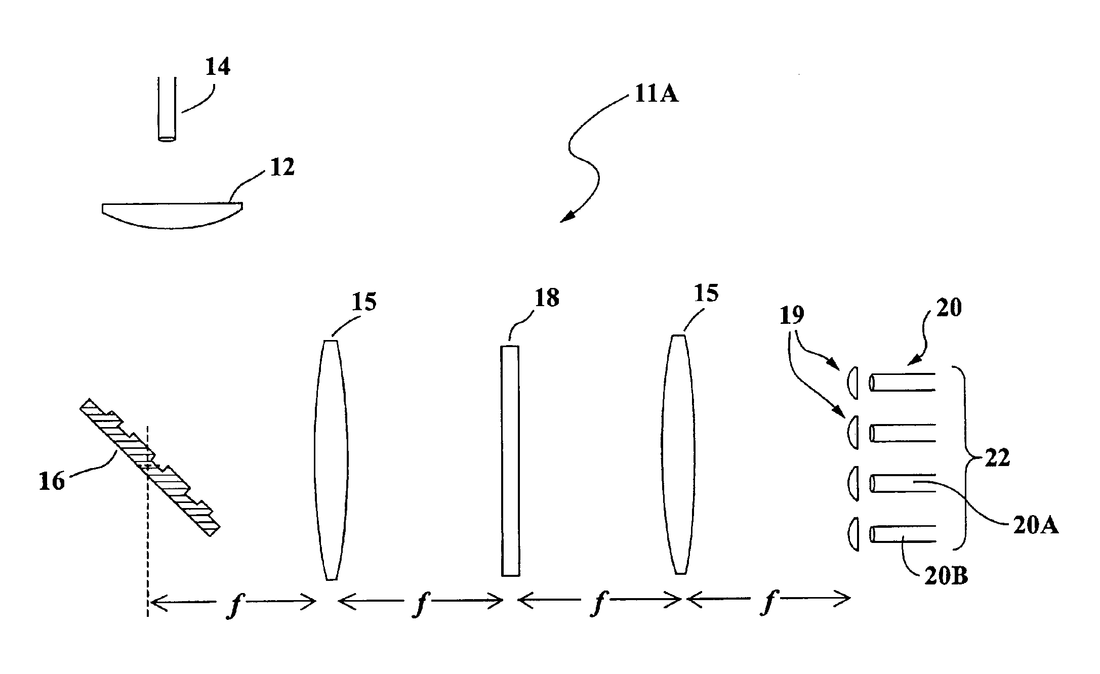
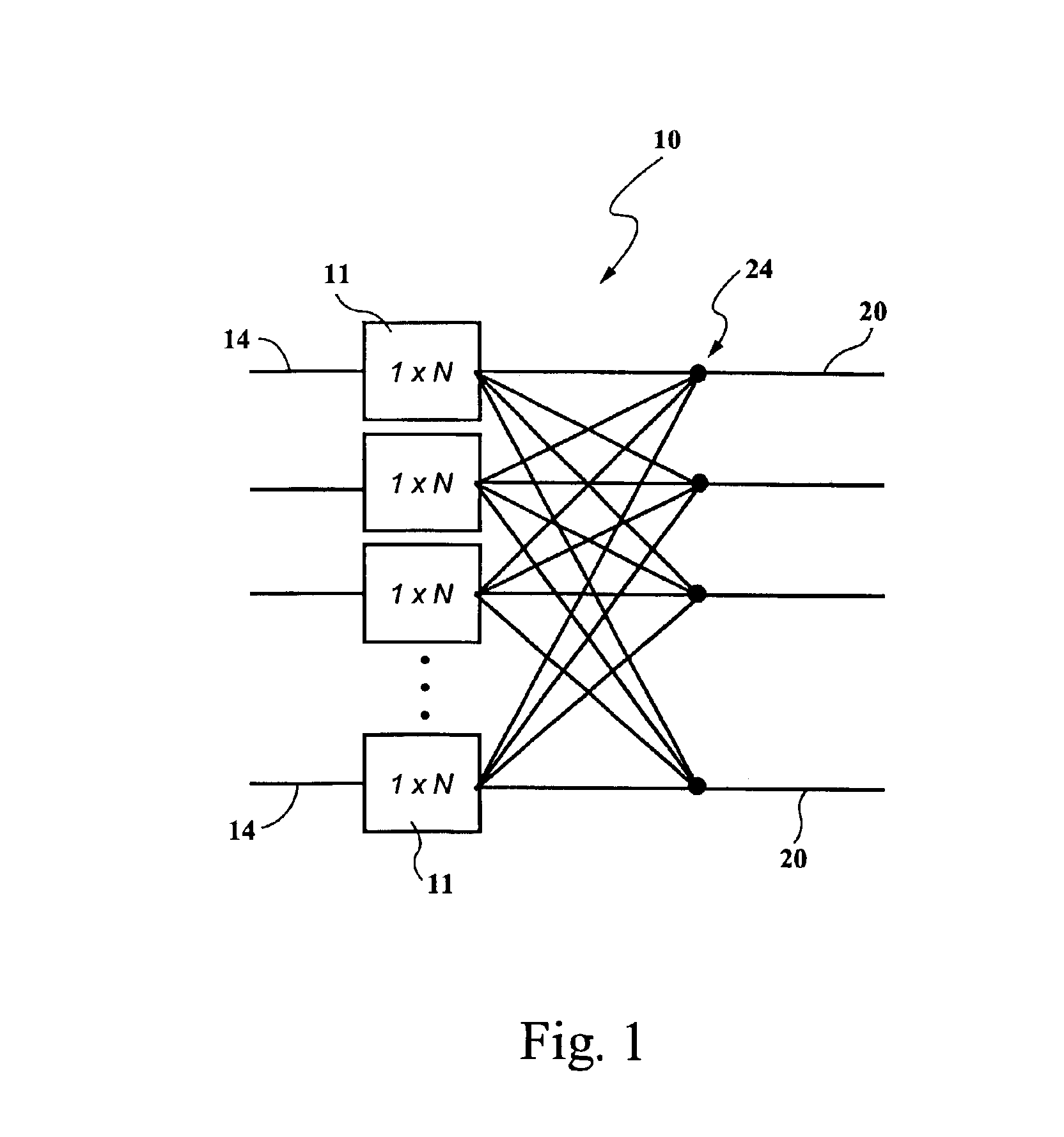
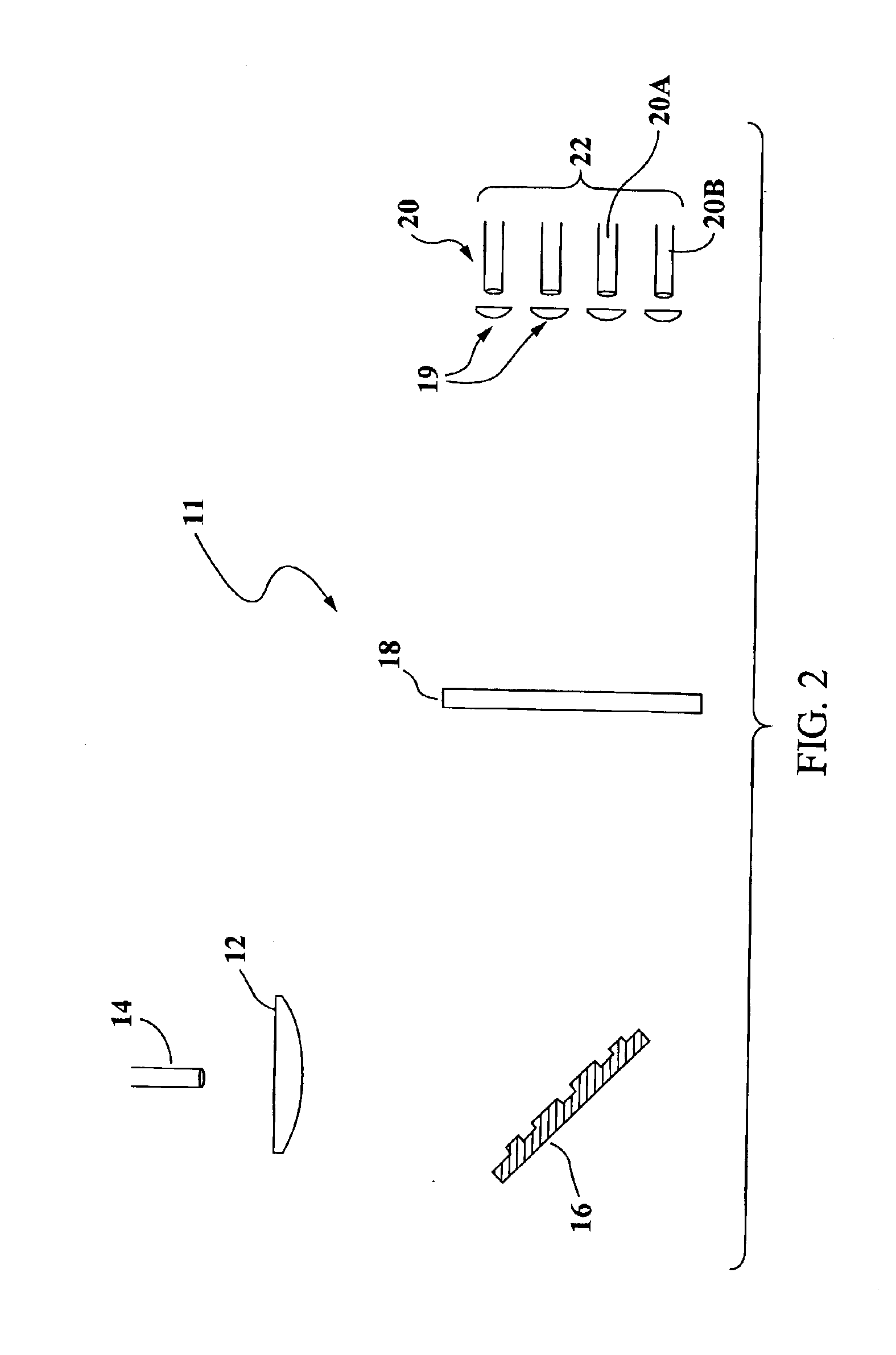
An embodiment 111C for implementing an (L×K)-switch (FIG. 9A) directly is depicted in FIG. 13. Light from each fiber 114A in an array of L input fibers 115 is collimated by its own micro-lens or GRIN lens 112A and directed onto its own the state selector 116A. Each state selector 116A imposes on its outgoing wavefront the same phase-only wave-amplitude profiles as before. The L state selectors 116A can either be individual units, or they can be integrated into a single unit, where different portions of a large SLM are used to spatially modulate the wavefronts from each input fiber. The output of all the state selectors 116A then enters a combiner 300 that projects the exit plane of each state selector 116A into the input aperture of the beam shaper 118. The combiner is an adaptation of DOEs that have been designed for implementing free-space optical interconnects for computer systems. Beam shaper 118 can use any of the previously-described DOEs. In the embodiment of FIG. 13, the wav...


PUM


Abstract

An optical cross-connect switch is disclosed which includes a plurality of optical input fibers, a plurality of optical output fibers and a plurality of the (1×N)-switches ganged together. Each of the switches includes a state selector, a lens for collimating light from a single one of the optical input fibers, a plurality of output coupling lenses, each of which corresponds to one of the optical output fibers, and a beam shaper for focusing light from the state selector onto a selected one of the coupling lenses for further focusing of the light onto the corresponding optical output fiber. Alternatively, the optical cross-connect switch can be a single an (L×K)-switch which includes a plurality of state selectors and a plurality of lenses for collimating light from the plurality of optical input fibers.

Description

FIELD OF THE INVENTIONThe present invention relates generally to optical beam-steering, spatial light modulation, diffractive optics and computer-generated holography, and more particularly to all-optical cross-connect switches which may be used in, inter alia, optical communication systems.BACKGROUND OF THE INVENTIONCurrently MEMS is the leading technology for implementing all-optical cross-connect switches for fiber optic telecommunication networks. Typically these devices work by collimating light from an array of input fibers and reflecting these light beams off an array of movable micromirrors, which then act to deflect each beam toward the appropriate output fiber. For large switches (more than 100 input and output fibers) the most popular configuration has the micromirrors arranged on a rectangular grid with their faces parallel to the substrate. The input light beams are directed at the micromirror array in the normal direction, and the mirrors tilt on two axes to deflect ea...

Claims


Application Information

Patent Timeline
IPC IPC(8): G02B6/35H04Q11/00
CPCG02B6/3516H04Q11/0005H04Q2011/0026H04Q2011/0052H04Q2011/0024G02B6/3548G02B6/356G02B6/3546
Inventor NOONAN, WILLIAM A.
Owner FOR NAT RES INITIATIVES
Why Eureka
Try Eureka