Turbulence-free laboratory safety enclosure

a laboratory and fume hood technology, applied in the field of controlled airflow and air distribution within the laboratory fume hood, can solve the problems of inability to know the exact solution and complex equations, and achieve the effect of eliminating turbulence, reducing slope angles, and improving turbulen

Inactive Publication Date: 2005-03-22
FLOW SCI INC
View PDF13 Cites 12 Cited by
  • Summary
  • Abstract
  • Description
  • Claims
  • Application Information

AI Technical Summary

Benefits of technology

It has been found that while a single airfoil vastly improves the turbulence inside a work chamber, a smaller less problematic reverse vortex exists directly behind the airfoil. The preferred embodiment described above eliminates this smaller vortex by positioning a second airfoil directly below a first. The second airfoil with an upwardly sloping section having a smaller slope angle eliminates the reverse vortex of the first. However, the second airfoil generates its own smaller reverse vortex. Therefore, a third airfoil with an upwardly sloping section having an even smaller slope angle can be added under the second to eliminate the vortex of the second airfoil. Additional airfoils with progressively smaller slope angles may be added to the stack, each eliminating the reverse vortex of the airfoil directly above. Within practical limits, the airfoil stack of the present invention can virtually eliminate turbulence within a work chamber. If the airfoil stack is attached to a movable sash door, a mechanical cam mechanism can be used to vary the angularity of the airfoils for maximum efficiency for all positions of the sash door. Furthermore, a stop on the sash door should be positioned such that the bottom airfoil of the airfoil deflector stack does not come to rest against any part of the fume hood when the sash door is in its closed position.

Problems solved by technology

The resultant equations are extremely complex and possess no known analytical (exact) solution.

Method used


Image

  • Turbulence-free laboratory safety enclosure
  • Turbulence-free laboratory safety enclosure
  • Turbulence-free laboratory safety enclosure

Examples


Embodiment Construction

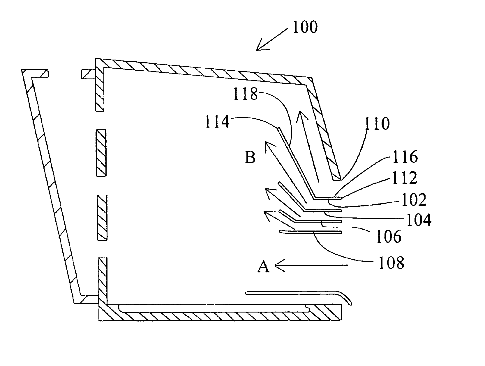
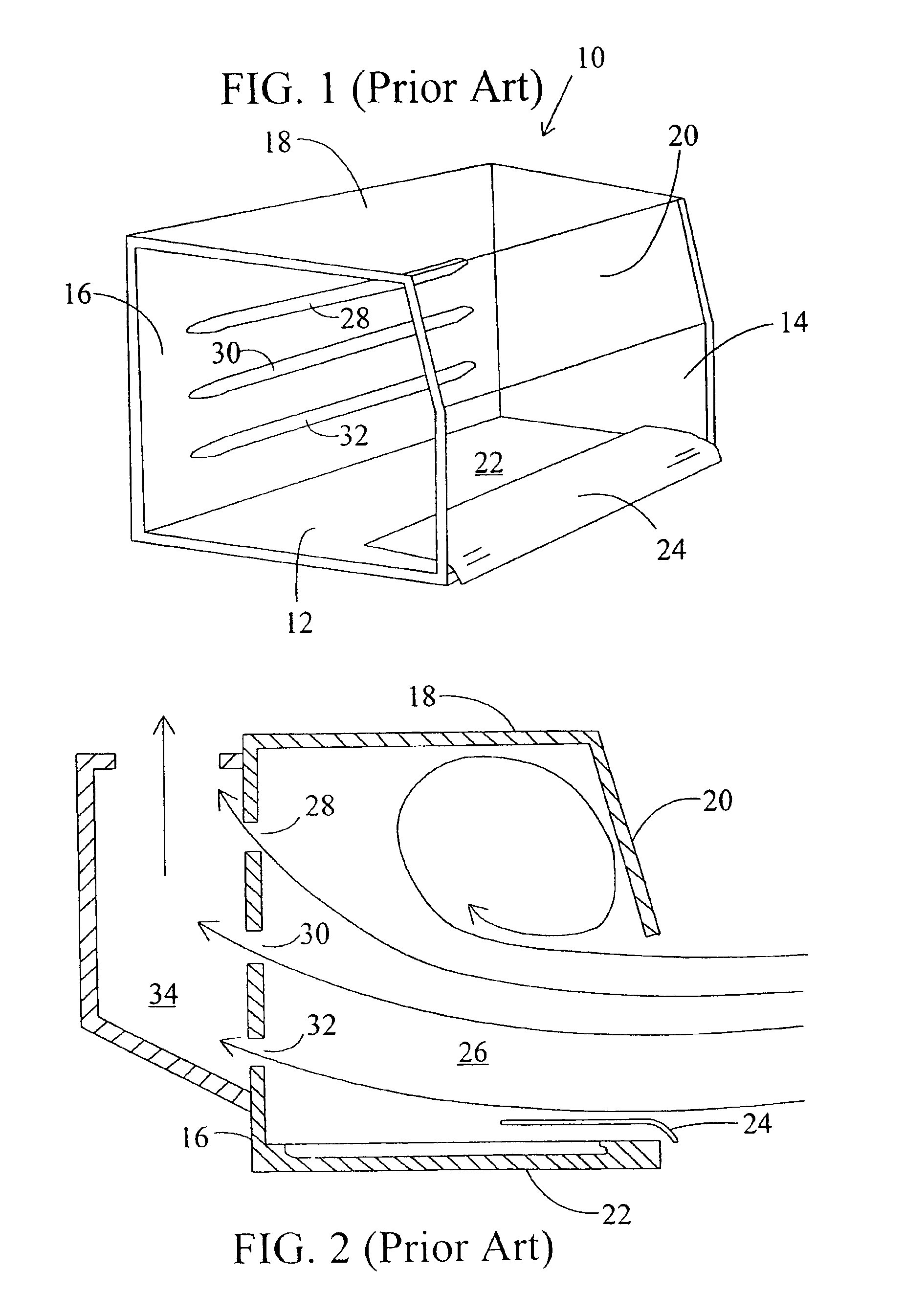
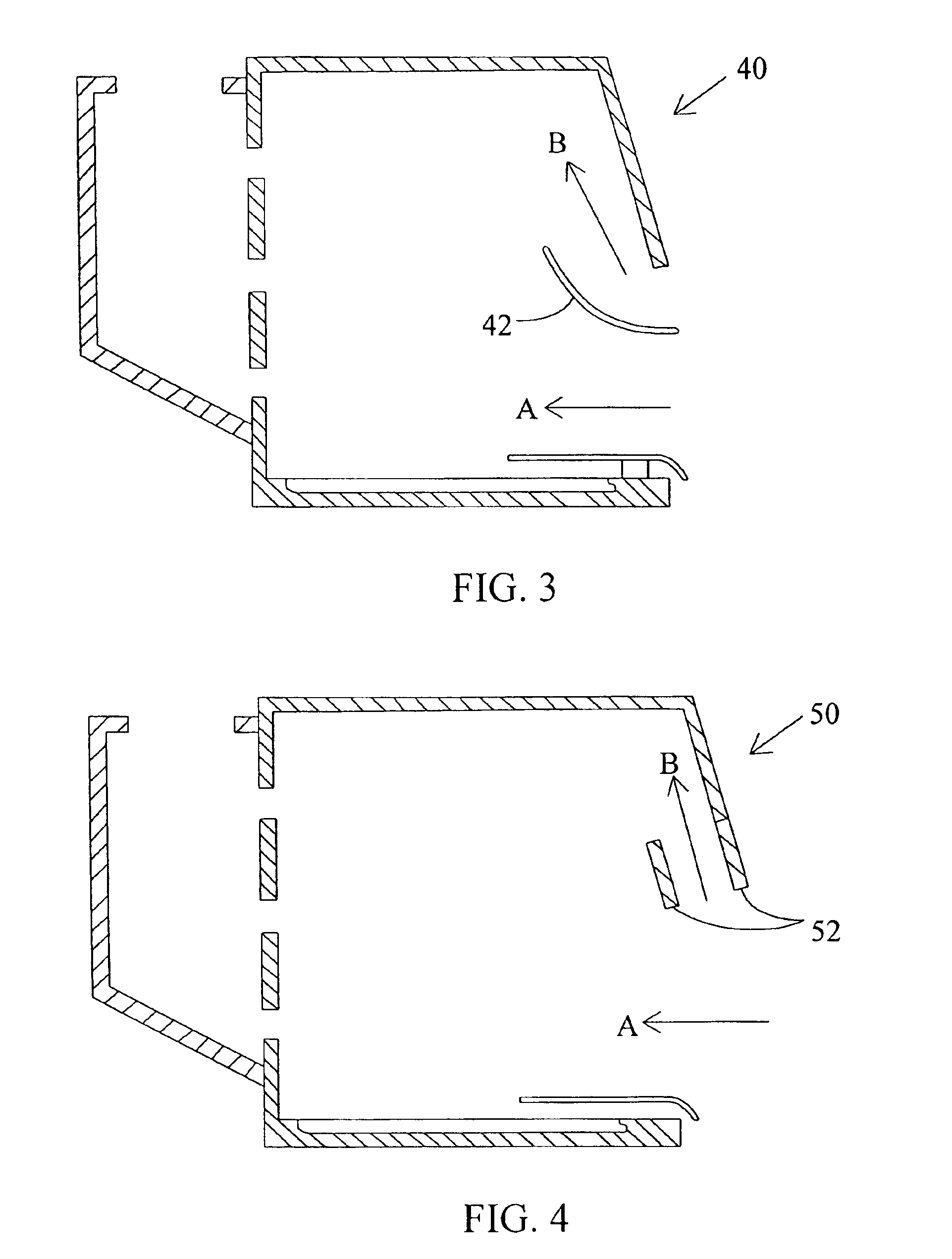
As best illustrated in FIGS. 1 and 2, enclosure 10 is comprised of spaced, parallel side walls 12 and 14; a rear wall 16; and an upper wall formed by a top wall 18 and a front wall 20, extending downwardly from the front edge of top wall 18. Enclosure 10 also includes a floor or bottom wall 22. A bottom airfoil 24 is mounted above the front edge of bottom wall 22 and is configured to enhance laminar airflow over bottom wall 22.

Walls 12-22 together define a work chamber 26 within which material is manipulated. The front edges of walls 12, 14, and 20, along with the leading edge of airfoil 24 define an operator access opening into chamber 26. Rear wall 16 includes horizontal, spaced openings 28, 30 and 32 to allow air to flow from chamber 26 into a plenum 34 through which the air is exhausted into an exhaust conduit (not shown).

Computer simulation and smoke tests performed on the fume hood of FIG. 1 have generated data used to analyze the airflow distribution shown in FIG. 2. Lines an...


PUM


Abstract

The present invention relates to controlled airflow and air distribution within a laboratory safety enclosure and in particular, to turbulence-free airflow within a laboratory fume hood. The fume hood of the present invention has a work chamber and an access opening having an upper edge. A horizontal air deflector structure is positioned adjacent to the upper edge of the access opening to divert a portion of air entering the access opening upwardly within the chamber, whereby the diverted air eliminates an airflow eddy current.

Description

BACKGROUND OF THE INVENTION1. Field of the InventionThe present invention relates to controlled airflow and air distribution within a laboratory safety enclosure and in particular, to turbulence-free airflow within a laboratory fume hood.2. Description of the Prior ArtFume hoods and laboratory safety enclosures are safety devices used in research, analytical, teaching, and other laboratories. These containment devices provide enclosed work areas where handling of toxic substances can be performed with minimum risk to users. They are used primarily in pharmaceutical, chemical, biological and toxicological laboratory settings.Specifically, a laboratory safety enclosure such as a fume hood also known as a ventilated workstation is comprised of an enclosure or chamber within which materials are manipulated or worked upon by an operator, and an air exhaust mechanism for removing air from the enclosure.The enclosure is comprised of a work chamber with an access opening and an exhaust or d...

Claims


Application Information

Patent Timeline
Patent Type & Authority Patents(United States)
IPC IPC(8): B08B15/00B08B15/02F24F3/16
CPCF24F3/1607B08B15/023F24F3/163
Inventor RYAN, RAYMOND F.KOLESNIKOV, ALEXY Y.
Owner FLOW SCI INC
Why Eureka
Try Eureka