
Methods and systems for improving the operation of transmissions for motor vehicles

a technology for motor vehicles and transmissions, applied in fluid gearings, manufacturing tools, gearings, etc., can solve the problems of adversely affecting the feel and firmness of the application of the converter clutch, and achieve the effects of reducing opposition, and reducing the application time of the converter clutch

Inactive Publication Date: 2005-03-29
TRANSGO LLC
View PDF11 Cites 8 Cited by
  • Summary
  • Abstract
  • Description
  • Claims
  • Application Information

AI Technical Summary

Benefits of technology

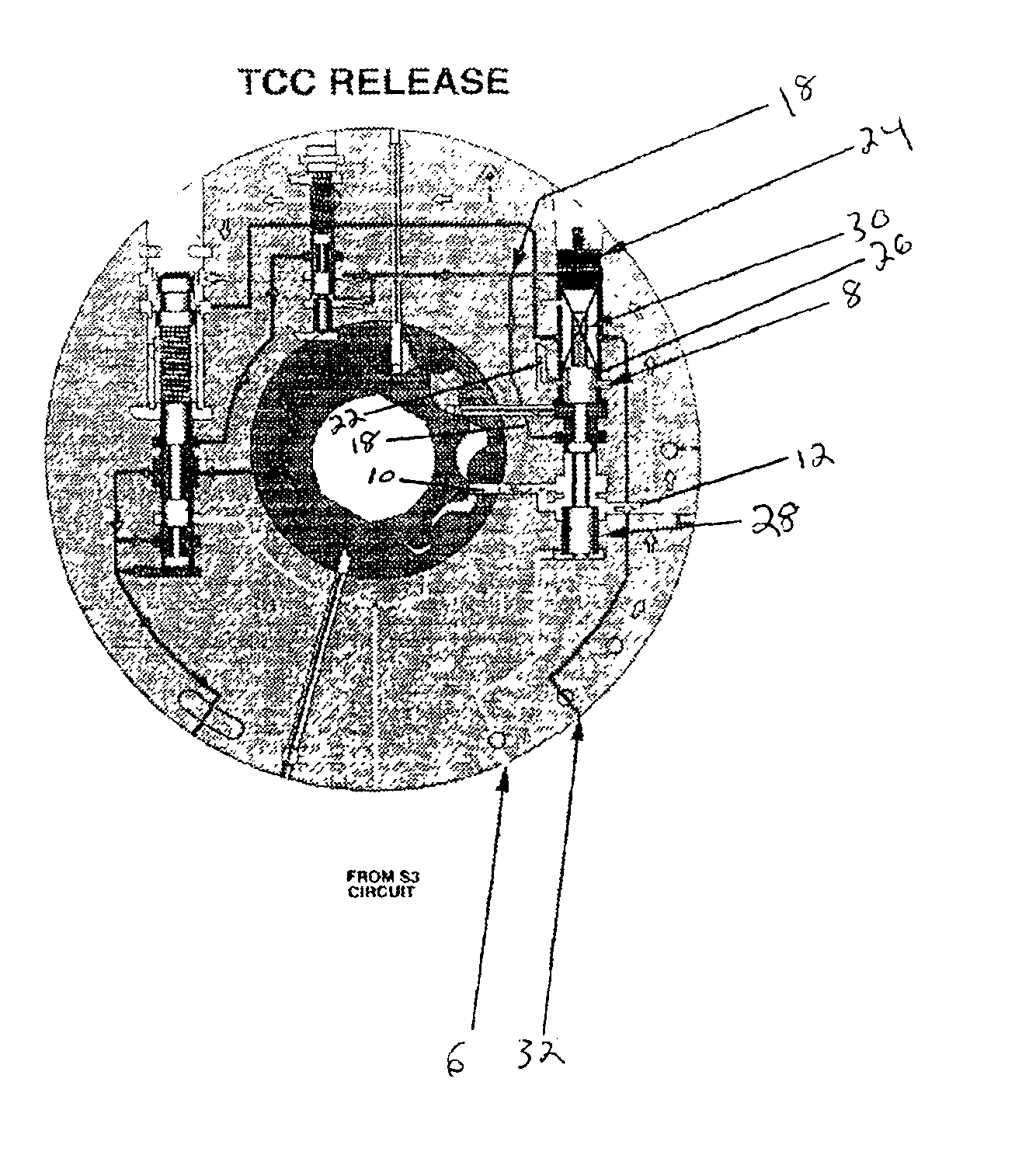
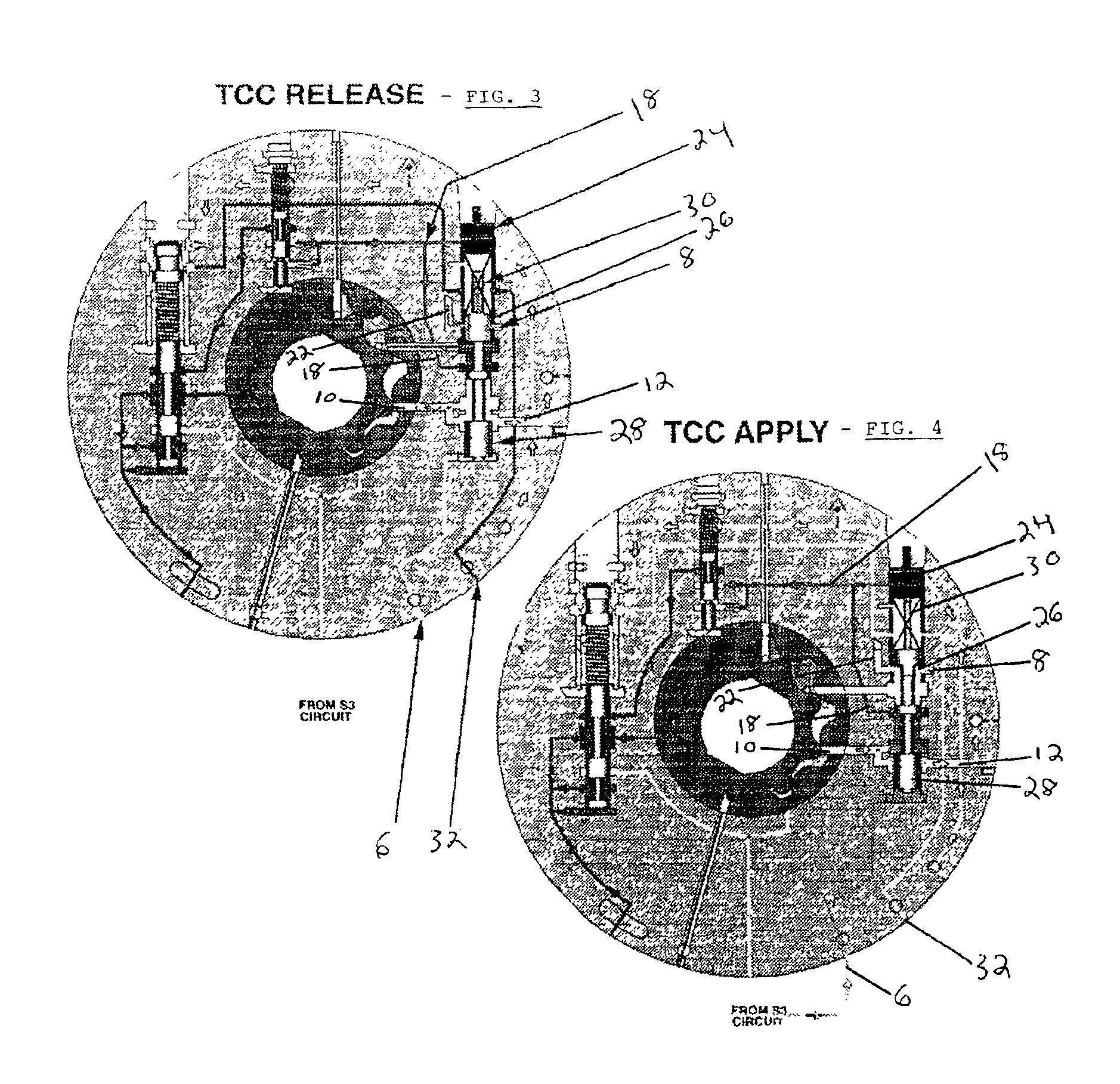
In accordance with the preferred embodiment of the present invention, a factory installed automotive transmission, and in particular the automotive transmission known as the “4R100” installed in automobiles manufactured by the Ford Motor Company, is modified to reduce the time required for applying the torque converter clutch by reducing the time required for the torque converter control valve to be moved into its uppermost position in response to an “ON” signal from an electronic control solenoid. Preferably, the apply time of the converter clutch will be reduced from the seven second interval of the “factory installed” transmission, to less than one second in the modified automotive transmission in accordance with the present invention.
In the preferred embodiments of the present invention, a balance valve which opposes the upward movement of the torque converter control valve in the 4R100 factory installed transmission, is removed, thereby reducing opposition to the upward movement of the torque converter control valve and decreasing the apply time of the converter clutch which corresponds to the time necessary for the torque converter control valve to move into its uppermost position. Additionally, the bushing or valve bore for the factory installed torque converter control valve is replaced by a new and longer bushing, which is oriented to partially block an exhaust oil passage in fluid communication with the valve bore of the factory installed transmission. Uncontrolled exhaust of converter oil through the exhaust passage in the factory installed transmission adversely affects the feel and firmness of the apply of the converter clutch. An orifice provided in the new valve bore is axially aligned with the exhaust passage of the factory installed transmission. The orifice has a smaller diameter than the diameter of the exhaust passage, thereby restricting the exhaust of fluid through the passage, and improving the feel and firmness of the application of the converter clutch. The size of the orifice can be adjusted to vary the feel of the converter clutch apply, as may be desired.
The modification of the components and hydraulics of the factory installed transmission in accordance with the present invention results in a faster apply time of the converter clutch in response to a signal from the electronic control solenoid, thereby reducing or eliminating the disadvantages resulting from the longer converter clutch apply time of the factory installed automotive transmission. Further modifications to the factory installed automotive transmission include replacing a return spring of the factory installed torque converter control valve with a stronger spring having a higher coefficient of tension, to increase the pressure of the regulated converter clutch charge oil, preferably from 140 pounds per square inch (psi) to 180 psi or greater, thereby further reducing the apply time of the converter clutch and increasing its ability to hold greater torque.

Problems solved by technology

Uncontrolled exhaust of converter oil through the exhaust passage in the factory installed transmission adversely affects the feel and firmness of the apply of the converter clutch.

Method used


Image

  • Methods and systems for improving the operation of transmissions for motor vehicles
  • Methods and systems for improving the operation of transmissions for motor vehicles
  • Methods and systems for improving the operation of transmissions for motor vehicles

Examples


Embodiment Construction

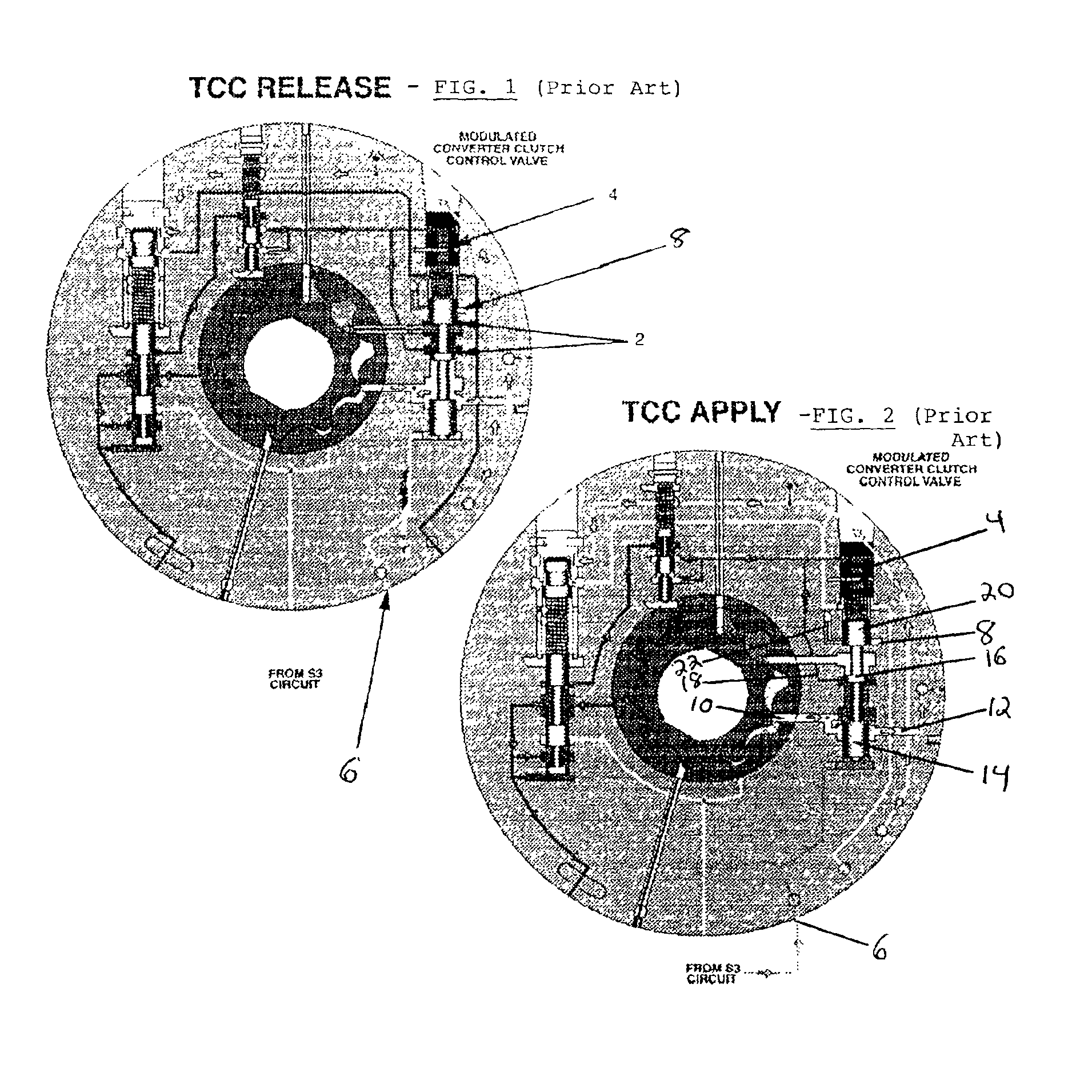
FIGS. 1 and 2 schematically illustrate a portion of the hydraulic circuity for the “factory installed” 4R100 automotive transmission, and in particular illustrate the torque converter control (TCC) system of the “factory installed” 4R100 transmission. FIG. 1 illustrates the position of the torque converter control valve when the converter clutch is released, while FIG. 2 illustrates the postion of the torque converter control valve when the converter clutch is applied.

The torque converter control valve, having upper and lower lands of different diameter, is generally illustrated by reference numeral 2. The difference in the diameter of the lands assists in moving the valve in an upward direction as shown in FIG. 1. A bushing and a small diameter valve are located at the top of the torque converter control valve 2, at a location generally designated by reference numeral 4. This upper valve, in cooperation with a return spring, opposes upward movement of the valve 2 when it is urged u...


PUM

PropertyMeasurementUnit
Pressureaaaaaaaaaa
Flow rateaaaaaaaaaa
Diameteraaaaaaaaaa

Abstract

The present application is directed to methods and systems for improving the operation of transmissions for automotive vehicles, and in particular, the “factory installed” automotive transmission installed by an original automobile manufacturer. The methods and systems modify both the structural components and hydraulic circuitry of an original automotive transmission to adjust applied pressure and shifting patterns to improve the efficient operation of the automotive transmission.

Description

BACKGROUND OF THE INVENTIONThe methods and systems of the present invention are directed to the modification and improvement of transmissions for automotive vehicles of the type installed by the original equipment manufacturers, commonly referred to as “factory installed”. The invention is particularly directed to the improvement and modification of the “factory installed” automotive transmission commonly known as the “4R100” installed in motor vehicles manufactured by The Ford Motor Company of Dearborn, Mich.The present inventor owns the following United States patents, the disclosure of each of which is expressly incorporated by reference into the present patent application: U.S. Pat. No. 4,449,426, issued on May 26, 1984; U.S. Pat. No. 4,711,140, issued on Dec. 8, 1987; U.S. Pat. No. 4,790,938, issued Dec. 13, 1988; U.S. Pat. No. 5,253,549, issued Oct. 19, 1993; U.S. Pat. No. 5,540,628, issued Jul. 30, 1996; U.S. Pat. No. 5,624,342, issued Apr. 29, 1998; U.S. Pat. No. 5,730,685, ...

Claims


Application Information

Patent Timeline
IPC IPC(8): F16H61/02F16H61/14
CPCF16H61/0267F16H61/14F16H2061/0062Y10T29/49721Y10T29/49233Y10T477/69368Y10T29/49716Y10T29/4973
Inventor YOUNGER, GILBERT W.
Owner TRANSGO LLC
Learn More