Power conversion circuit having off-voltage control circuit

a power conversion circuit and control circuit technology, applied in the direction of dynamo-electric converter control, motor/generator/converter stopper, dc motor speed/torque control, etc., can solve the problems of power conversion device failure, control terminal voltage may possibly exceed the threshold voltage breakage of the switching element, so as to avoid short circuit through upper and lower arms, reduce the effect of short circuit and high reliability

Active Publication Date: 2013-01-29
PANASONIC CORP
View PDF8 Cites 10 Cited by
  • Summary
  • Abstract
  • Description
  • Claims
  • Application Information

AI Technical Summary

Benefits of technology

[0045]As described above, according to the present invention, an arm drive signal having a voltage lower than a predetermined off voltage is output during the time period from termination of turn-off operation of the corresponding arm until start of turn-on operation of the other arm. Thereafter, immediately after termination of the turn-on operation of the other arm, the voltage of the arm drive signal is returned to the predetermined off voltage. Therefore, it is possible to greatly shorten the duration of application of a voltage lower than the predetermined off voltage that is applied to the control terminal to turn off the arm made of a switching element, and thus avoid malfunction due to application of high dv / dt. As a result, a power conversion circuit with high reliability can be presented, in which short-circuiting through the upper and lower arms can be avoided, and the life of the switching element is greatly improved.
[0046]In particular, the time points of termination of turn-off operation of the corresponding arm and turn-on operation of the other arm are grasped by detecting the main terminal voltages, the main terminal currents, or the control terminal voltages of the arms directly. Therefore, with correct detection of the time points of termination of turn-off operation of the corresponding arm and turn-on operation of the other arm, it is possible to minimize the duration of application of a voltage lower than the predetermined off voltage applied to the control terminal of the switching element of the arm, and thus avoid malfunction due to application of high dv / dt effectively.
[0049]When the arm temperature becomes high, the threshold voltage of the arm (reference voltage with which the arm is turned on) becomes low, and thus the arm that is off becomes easy to turn on with a comparatively low off voltage. However, since the off voltage applied to the control terminal of the arm that is off is further reduced, such unnecessary turn-on operation is less likely to occur. Accordingly, malfunction due to application of high dv / dt can be stably avoided.
[0050]As described above, according to the power conversion circuit of the present invention, when a voltage lower than a predetermined off voltage is applied to the control terminal of a switching element as an arm, the duration of the application is greatly shortened, and yet malfunction due to application of high dv / dt can be avoided. Therefore, it is possible to present a power conversion circuit with high reliability in which short-circuiting through upper and lower arms is avoided and the life of the switching element is greatly improved.

Problems solved by technology

When such operation occurs, the voltage of the control terminal may possibly exceed the threshold voltage of the switching element.
If the voltage of the control terminal changes and exceeds the threshold voltage during a predetermined break period, the upper and lower arms will conduct simultaneously causing short-circuiting, resulting in breaking of the switching element, and moreover failure of the power conversion device.
If the switching time dVdc / dt of the upper arm 21u during its turn-on operation is reduced, the switching speed of the upper arm 21u will be reduced, resulting in increase in switching loss.

Method used


Image

  • Power conversion circuit having off-voltage control circuit
  • Power conversion circuit having off-voltage control circuit
  • Power conversion circuit having off-voltage control circuit

Examples


first embodiment

[0067](First Embodiment)

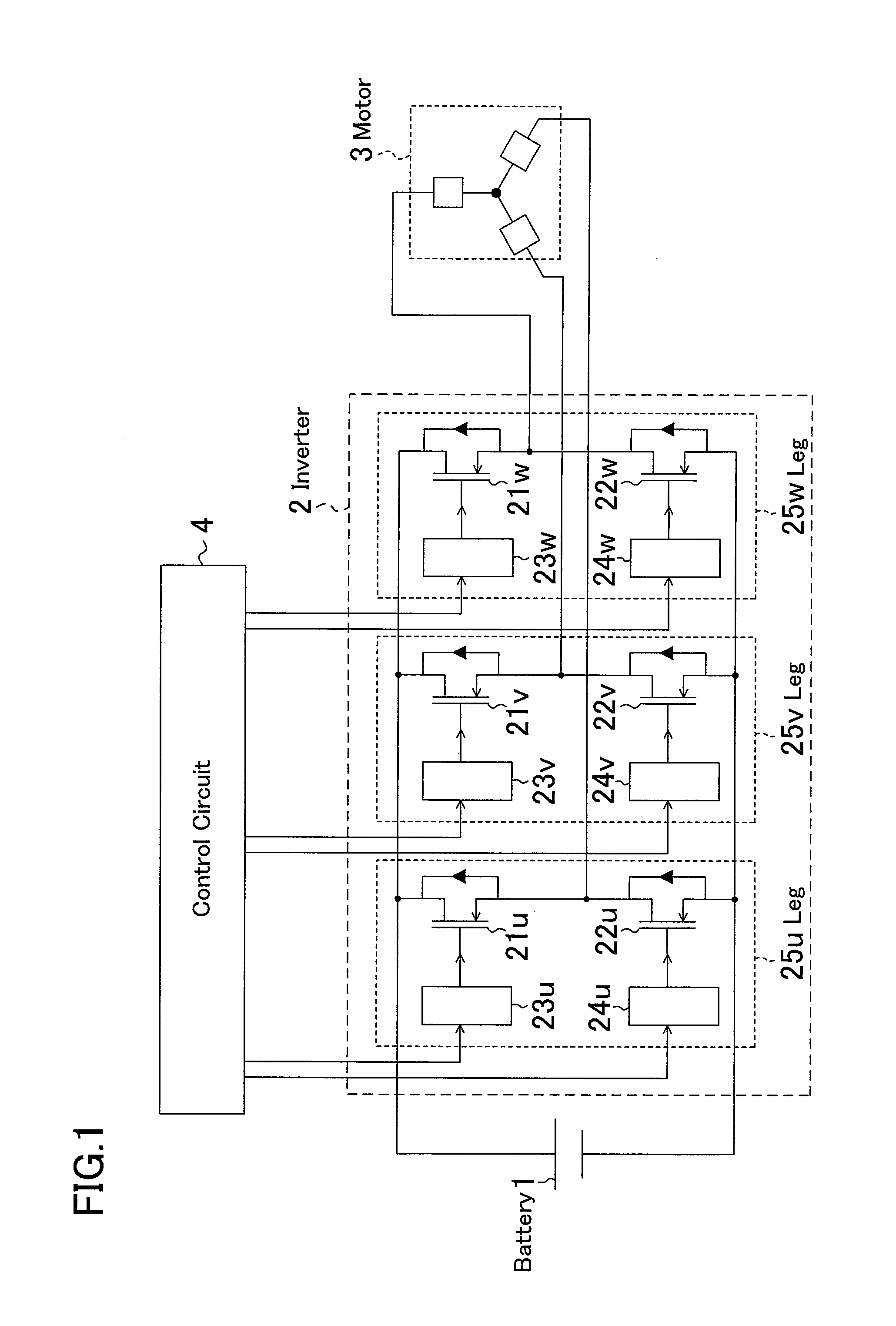
[0068]FIG. 1 is a schematic circuit diagram of a motor drive system, presented to illustrate an inverter of a first embodiment to which the present invention is applied. Herein, as an example, MOSFETs are used as switching elements. The motor drive system is constructed of a battery 1, an inverter 2, a motor 3, and a control circuit 4.

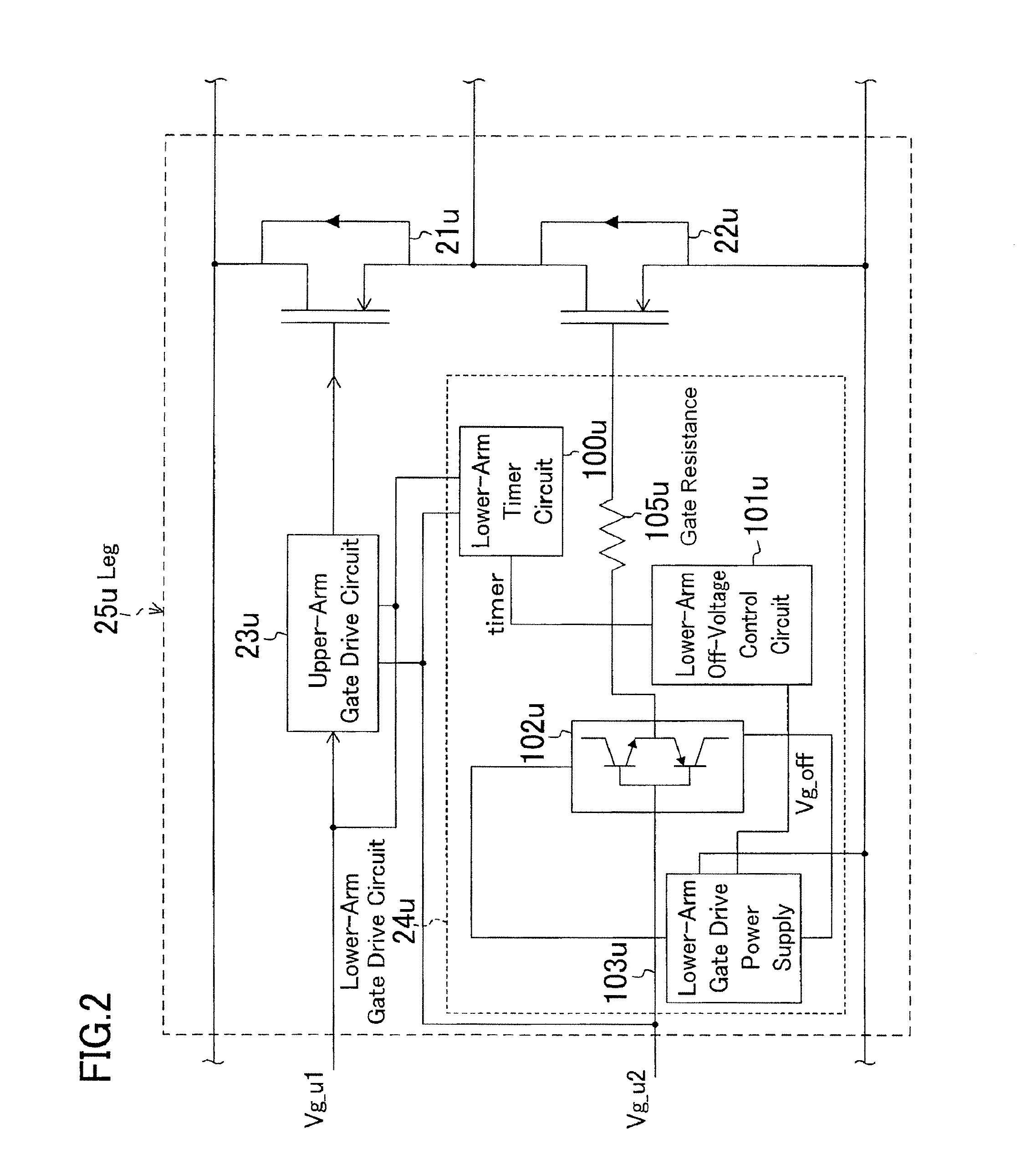
[0069]The battery 1 supplies DC power to the inverter 2. The inverter 2 converts the DC power supplied from the battery 1 to AC power and supplies the AC power to the motor 3. The motor 3 revolves with the AC power supplied from the inverter 2. The control circuit 4 controls the inverter 2 so that the motor 3 operates as desired. The inverter 2 is constructed of the same number of legs (25u, 25v, 25w) as the number of kinds of AC power to be output. The legs 25u, 25v, and 25w respectively include: upper arms 21u, 21v, and 21w (positive side) and lower arms 22u, 22v, and 22w (negative side) connected in series between the positiv...

second embodiment

[0087](Second Embodiment)

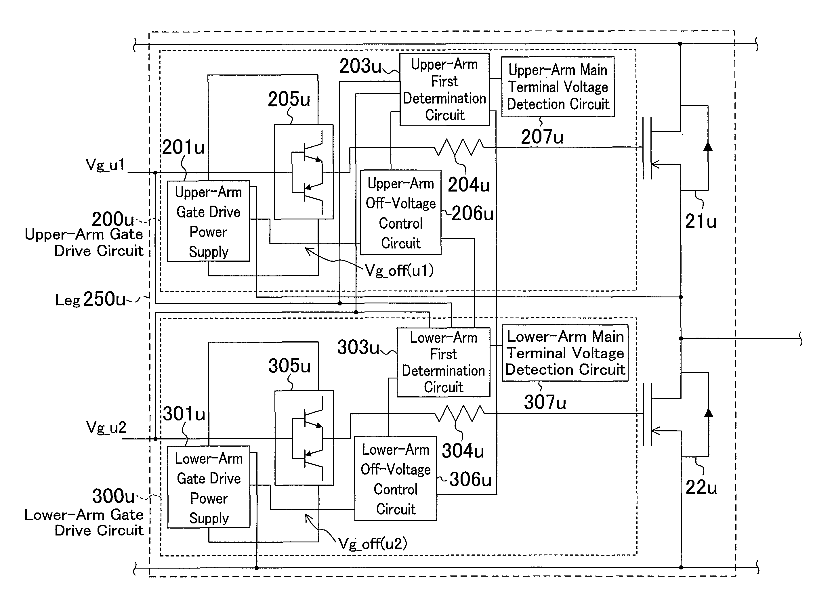
[0088]FIG. 5 is a schematic circuit diagram of a motor drive system, presented to illustrate an inverter of a second embodiment to which the present invention is applied. FIG. 5 is different from FIG. 1 only in that the legs 25u, 25v, and 25w are replaced with legs 250u, 250v, and 250w. The other configuration is the same as that of FIG. 1.

[0089]FIG. 6 is a circuit diagram presented to illustrate the leg 250u in FIG. 5 in detail. The leg 250u includes an upper arm 21u and a lower arm 22u and their corresponding upper-arm gate drive circuit 200u and lower-arm gate drive circuit 300u.

[0090]The upper-arm gate drive circuit 200u includes an upper-arm gate drive power supply 201u, an upper-arm first determination circuit 203u, an upper-arm gate resistance 204u, an upper-arm arm-drive circuit 205u, an upper-arm off-voltage control circuit 206u, and an upper-arm main terminal voltage detection circuit 207u. The lower-arm gate drive circuit 300u includes a lower-ar...

third embodiment

[0115](Third Embodiment)

[0116]Another embodiment of the present invention will be described with reference to FIG. 8.

[0117]FIG. 8 is a circuit diagram presented to illustrate the leg 250u in FIG. 5 in detail. The circuit diagram of FIG. 8 is different from that of FIG. 6 in that the upper-arm main terminal voltage detection circuit 207u and the lower-arm main terminal voltage detection circuit 307u are replaced with an upper-arm main terminal current detection circuit 217u and a lower-arm main terminal current detection circuit 317u, and that the upper-arm first determination circuit 203u and the lower-arm first determination circuit 303u are replaced with an upper-arm second determination circuit 213u and a lower-arm second determination circuit 313u. The other configuration is the same as that of FIG. 6, and thus description thereof is omitted here.

[0118]The upper-arm main terminal current detection circuit 217u and the lower-arm main terminal current detection circuit 317u respec...


PUM


Abstract

In a power conversion circuit operating with high frequency, an off-voltage control circuit 101u of a lower-arm gate drive circuit 24u controls the output voltage of a gate drive power supply 103u to change the output voltage to a voltage lower than a predetermined off voltage during a time period from termination of turn-off operation of a lower arm 22u until start of turn-on operation of an upper arm 21u, and thereafter return the output voltage to the predetermined off voltage immediately after termination of the turn-on operation of the upper arm 21u. With this control, short-circuiting through the upper and lower arms occurring due to a high voltage change dv / dt can be avoided, and the life of a switching element constituting the power conversion circuit improves, increasing the reliability of the power conversion circuit.

Description

RELATED APPLICATIONS[0001]This application is the U.S. National Phase under 35 U.S.C. §371 of International Application No. PCT / JP2009 / 006930, filed on Dec. 16, 2009, which in turn claims the benefit of Japanese Application No. 2008-320956, filed on Dec. 17, 2008, the disclosures of which Applications are incorporated by reference herein.TECHNICAL FIELD[0002]The present disclosure relates to a power conversion circuit that is constructed of a plurality of upper and lower arms and, in particular, operates with large power and high frequency.BACKGROUND ART[0003]In recent years, switching elements (IGBTs, MOSFETs, and JFETs) included in power conversion devices such as inverters and converters have become increasingly high in voltage resistance and speed. In this situation, research and development has been actively conducted on power conversion devices, for increasing the power of power conversion devices using switching elements with high voltage resistance, and for reducing the size...

Claims


Application Information

Patent Timeline
Patent Type & Authority Patents(United States)
IPC IPC(8): H02M7/537H02P1/00
CPCH02M1/28
Inventor TAGOME, MASAKIKITABATAKE, MAKOTOKAZAMA, SHUN
Owner PANASONIC CORP
Why Eureka
Try Eureka