Slide drive apparatus and slide drive method for pressing machine

Inactive Publication Date: 2005-03-29
KOMATSU LTD +1
View PDF12 Cites 29 Cited by
  • Summary
  • Abstract
  • Description
  • Claims
  • Application Information

AI Technical Summary

Benefits of technology

According to the above constitution, since the die height adjustment is performed by the position control of the servo motor during driving of the slide, the die height adjustment can be performed with very high precision, and the product precision can be enhanced dramatically. Further, even when the slide drive source is not a servo motor, but, for example, a DC motor, an AC motor or the like, if the position control of the servo motor for adjusting the die height is performed by rece

Problems solved by technology

Recently, there are more and more products that require very high product precision, and this problem becomes important.
Consequently, the positioning precision, at the time of adjustment of the die height, cannot be made so high, thus making it very difficult to apply the apparatus to the products requiring high precision.
In addition,

Method used


Image

  • Slide drive apparatus and slide drive method for pressing machine
  • Slide drive apparatus and slide drive method for pressing machine
  • Slide drive apparatus and slide drive method for pressing machine

Examples


first embodiment

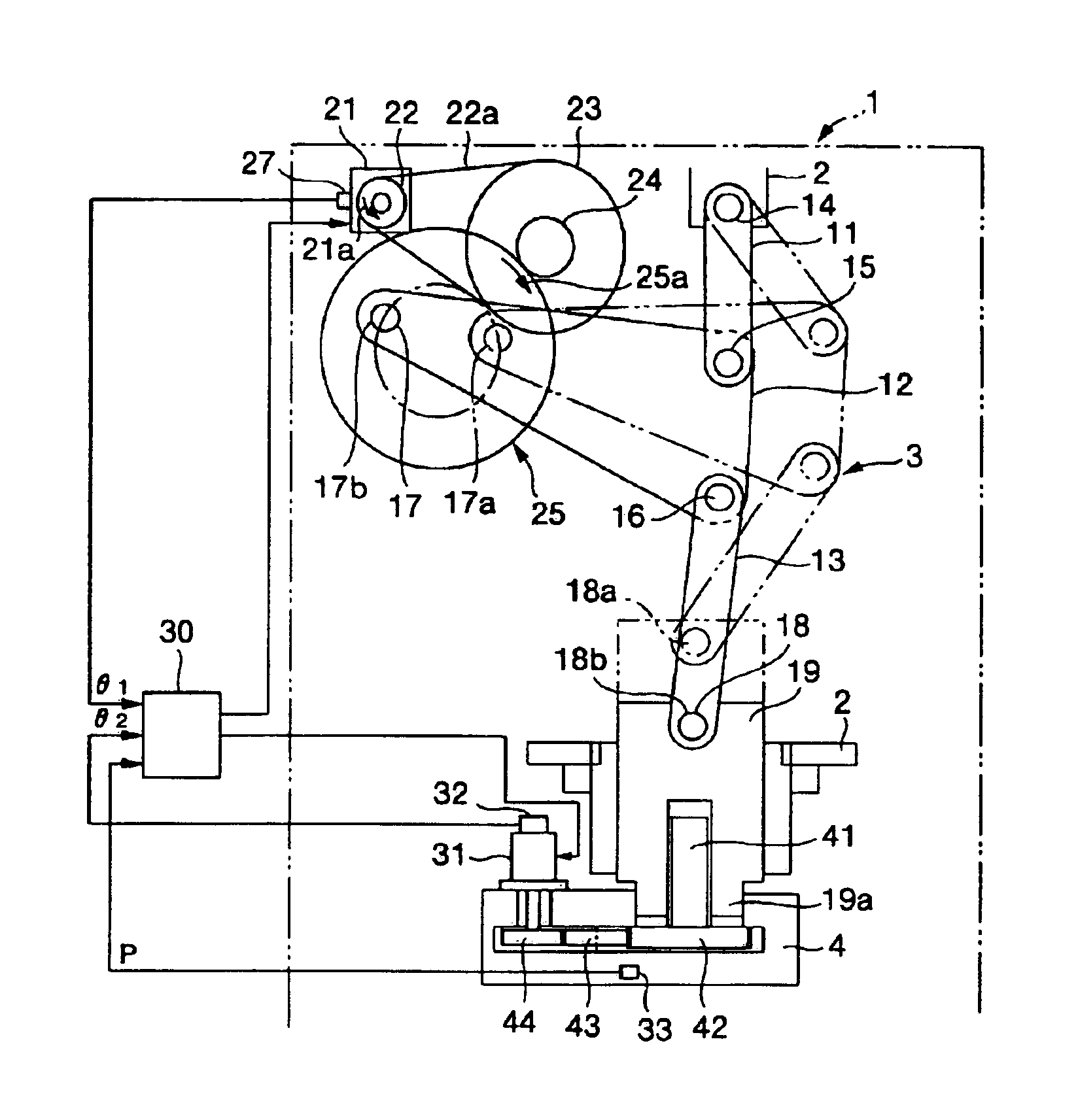
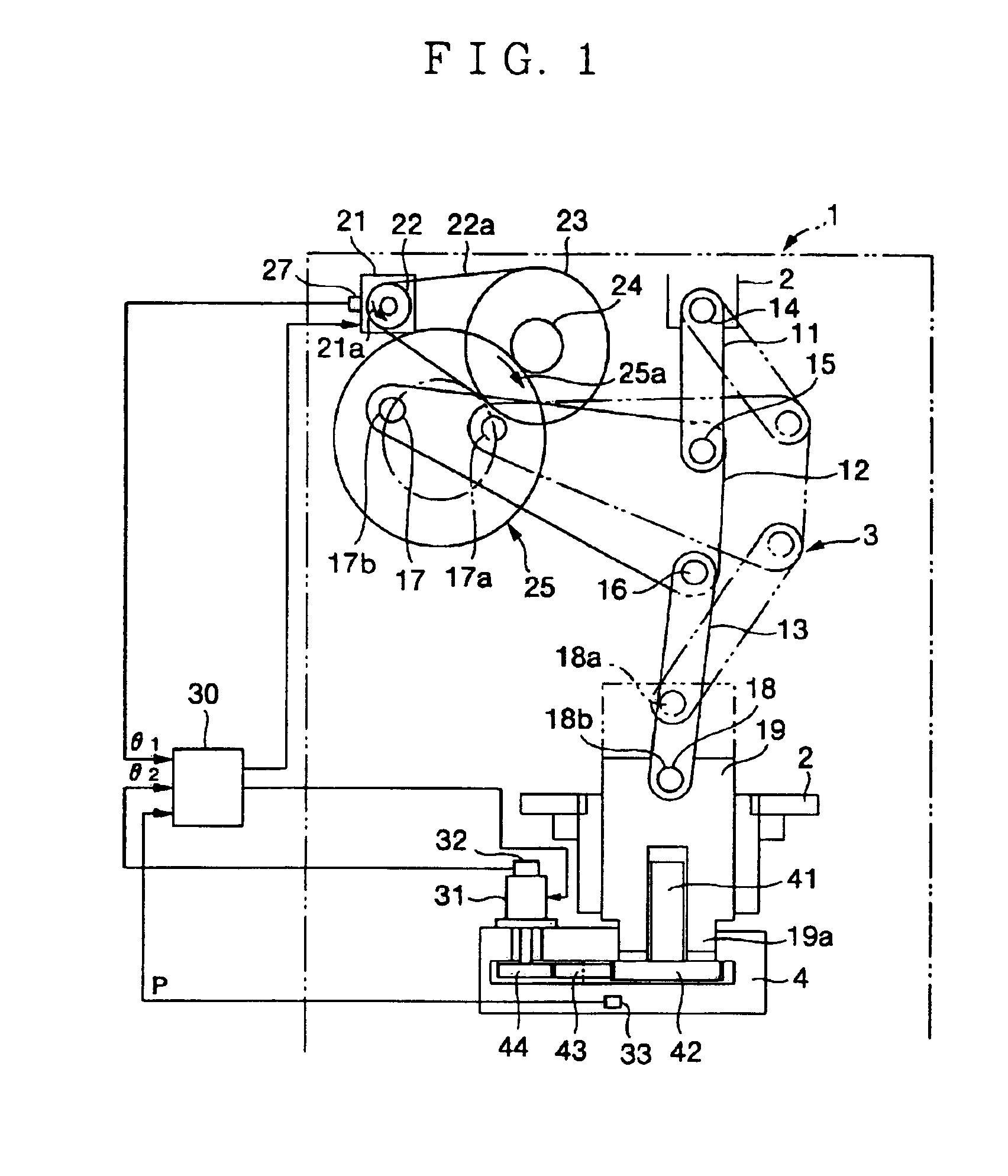
A first embodiment will be explained based on FIG. 1. FIG. 1 is a schematic block diagram of this embodiment. In FIG. 1, a slide 4 and a plunger 19 of a pressing machine 1 are both supported at a main body frame 2 to be vertically movable, and the slide 4 and the plunger 19 are fitted at a lower protruded portion 19a of the plunger 19 to be vertically slidable. A thread portion of an adjusting screw 41 provided at the slide 4 is screwed into a female screw portion formed in a lower part of the plunger 19. An upper part of the plunger 19 is connected to the main body frame 2 via a link mechanism 3. Namely, one end of a first link 11 is rotatably connected to an upper part of the main body frame 2 with a pin 14, the other end thereof is connected to one end of both end portions of one side of a triangle link 12. The other end of the both end portions of the aforementioned one side of the triangle link 12 is connected to one end of a second link 13 with a pin 16, and the other end of t...

second embodiment

Next, a second embodiment will be explained based on FIG. 4. FIG. 4 is a schematic block diagram of a press drive apparatus of this embodiment, and the same components as in FIG. 1 are given the same reference numerals and symbols in FIG. 4, and the explanation will be omitted below. A pinion 51 attached to an output shaft of a servo motor 21 for driving a slide is meshed with a gear 52, and a nut member 54 is fixedly provided at an axis of the gear 52, the nut member 54 is rotatably supported at a main body frame 2. A ball screw 53 is screwed into the nut member 54 to be movable in the axial direction. A tip end portion of the ball screw 53 is caught by a long hole 55 longer in a perpendicular direction to the axis of the ball screw and an catching pin 56, which are formed at a triangle link 12 of a link mechanism 3, to be vertically slidable to be connected thereto.

Next, an operation of this embodiment will be explained with reference to FIG. 4. When the servo motor 21 is rotated,...

third embodiment

Next, a third embodiment will be explained base on FIG. 5. The same components as in FIG. 1 are given the same numerals and symbols, and the explanation thereof will be omitted here. A pinion 51 attached to an output shaft of a servo motor 21 is meshed with a gear 52, a ball screw 53a is attached at an axis of the gear 52, and a ball screw 53a is rotatably supported at a main body frame 2. A nut member 54a is screwed onto a ball screw 53a to be movable in an axial direction. An upper part of a link 66 is swingably connected to the nut member 54a with a pin, and an upper part of a plunger 19 is connected to a lower part of the link 66 with a pin 18. The ball screw 53a, the nut member 54a and the link 66 constitute a ball screw mechanism 5.

Here, an operation of the third embodiment will be explained. When the servo motor 21 is rotated, the ball screw 53a is rotated, and following this, the nut member 54a is moved in the axial direction (the horizontal direction in this example). The m...


PUM

PropertyMeasurementUnit
Poweraaaaaaaaaa
Transmissionaaaaaaaaaa
Heightaaaaaaaaaa

Abstract

A slide drive apparatus and a slide drive method for a pressing machine capable of enhancing positioning precision at the time of adjustment of die height, and responding to pressing work at high stroke per minute. For this purpose, the drive apparatus includes a slide (4), a servo motor (21) for controlling slide motion, a mechanical power transmission mechanism (3, 5, 6) for converting rotational power of the servo motor for controlling slide motion into reciprocating motion of the slide, and a servo motor (31) for adjusting die height, which performs die height adjustment of the slide by a position control.

Description

TECHNICAL FIELDThe present invention relates to a slide drive apparatus and a slide drive method for a pressing machine.BACKGROUND ARTSince a temperature difference occurs to a each component frame while a pressing machine is used, the die height is changed, and when high product precision is required, the change in die height has a large influence on the product precision. Recently, there are more and more products that require very high product precision, and this problem becomes important. For such a change in die height, a die height adjusting apparatus is conventionally proposed, and the one disclosed in, for example, Japanese Utility Model Application Publication No. 3-29036 is known. FIG. 7 is a block diagram of a die height adjusting apparatus described in Japanese Utility Model Application Publication No. 3-29036.In FIG. 7, a slide 4 is connected to a plunger 19 operated in a vertical direction via an adjusting screw 41, and by rotating the adjusting screw 41, the position ...

Claims


Application Information

Patent Timeline
IPC IPC(8): B21J9/18B21J13/00B21J9/00B21J13/08B30B1/10B30B15/00B30B1/00B30B1/26B30B1/14B30B15/06B30B1/18
CPCB21J9/18B21J13/085B30B1/008B30B15/0094B30B1/266B30B15/0035B30B15/0041B30B1/14
Inventor TERAOKA, KENICHI
Owner KOMATSU LTD
Why Eureka
Try Eureka