Reverse-input shutoff clutch and rotation drive device
a technology of reverse-input shutoff and rotation drive, which is applied in the direction of interengaging clutches, couplings, wing accessories, etc., can solve the problems of change in the rotational resistance of the seal, leakage of viscous fluid, and start-up response, and achieve excellent start-up response
- Summary
- Abstract
- Description
- Claims
- Application Information
AI Technical Summary
Benefits of technology
Problems solved by technology
Method used
Image
Examples
first embodiment
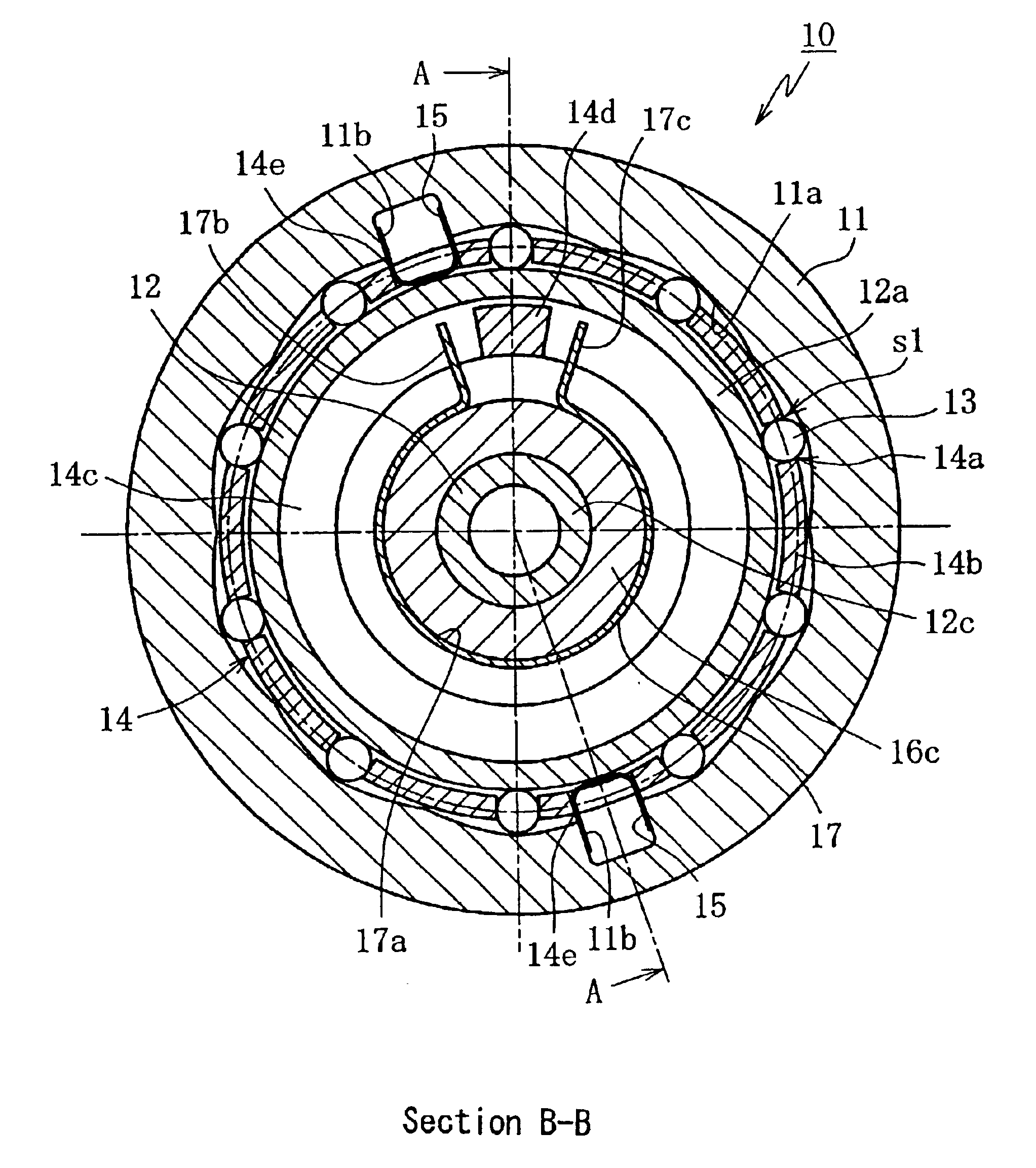
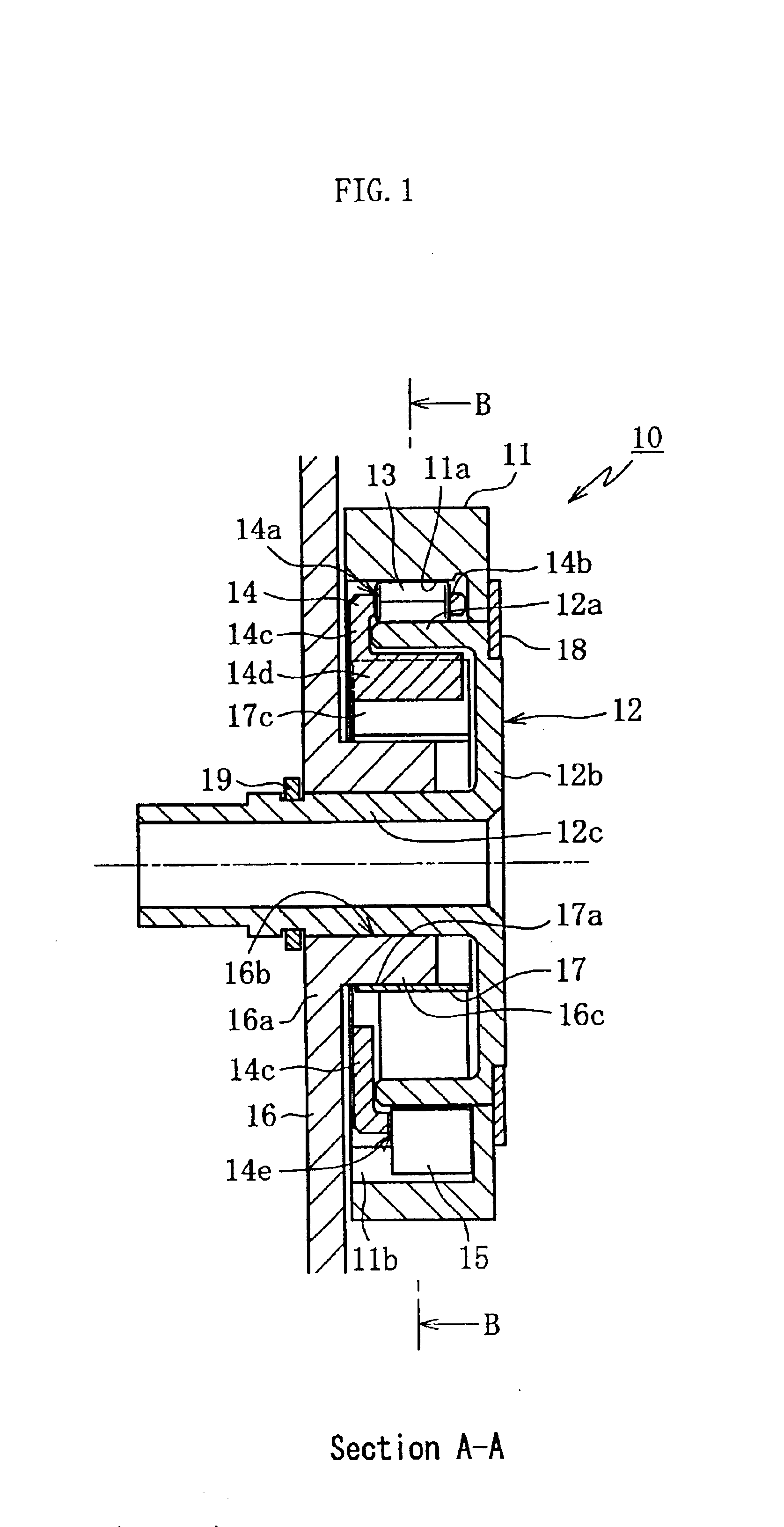
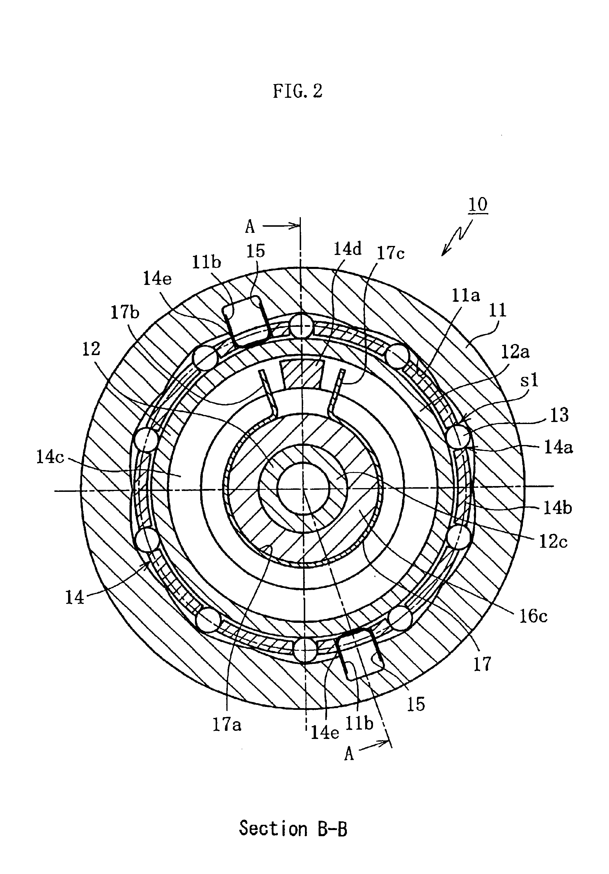
FIGS. 1 and 2 show a reverse-input shutoff clutch 10 of an outer-ring input type according to the invention.
The clutch 10 is provided with an input inner ring 11 as an input-side rotation member, an output inner ring 12 as an output-side rotation member, rollers 13 as a torque transmission member, a cage 14 for retaining the rollers 13, a centering spring 15 as an elastic member for positioning the cage 14, a housing 16 as a stationary-side member, and a sliding spring 17 as rotational resistance applying means for causing slide friction resistance to act on the cage against the rotation of the cage 14.
The input outer ring 11 is connected, either directly or indirectly through power transmission means such as chain, to a drive portion (not shown; constituted with, for example, an electric motor and a speed reduction mechanism).
The output inner ring 12 is, as shown in FIG. 1, arranged at the inside diameter side of the input outer ring 11. Also, the output inner ring 12 is provided w...
second embodiment
Next, the invention will be described below, where the reverse-input shutoff clutch 10 of an inner ring input type is applied to an axle shaft portion of an electricity-assisted trolley.
The clutch 10 is, as shown in FIG. 10, provided with a clutch inner ring 42 mounted on a axle shaft 41 as a an input-side rotation member, a clutch outer ring 43 mounted on a housing 44 as an output-side rotation member, rollers 45 as torque transmission members, a cage 46, a centering spring 47 as an elastic member, a vehicle-body frame 48 and a sliding spring installation ring 49, both of which as stationary-side members, and a sliding spring 50 for applying rotational resistance to the cage 46. The connection between the axle shaft 41 and the clutch inner ring 42 as well as that between the housing 44 and the clutch outer ring 43 may be made by means such as a multi-faced joint structure, spline, serration or key. The “multi-faced joint structure” means, in general, a connection structure where on...
PUM
 Abstract
Description
Claims
Application Information
 - R&D
- Intellectual Property
- Life Sciences
- Materials
- Tech Scout
- Unparalleled Data Quality
- Higher Quality Content
- 60% Fewer Hallucinations
Browse by: Latest US Patents, China's latest patents, Technical Efficacy Thesaurus, Application Domain, Technology Topic, Popular Technical Reports.
© 2025 PatSnap. All rights reserved.Legal|Privacy policy|Modern Slavery Act Transparency Statement|Sitemap|About US| Contact US: help@patsnap.com


