Supercharge Your Innovation With Domain-Expert AI Agents!

Ink jet head and method for the manufacture thereof

a jet head and jet technology, applied in the field of jet head, can solve the problems of water repellent thin films that are likely to peel off and undergo a drop in abrasion resistance, distortion of film shape, and cracks, and achieve the effects of less peeling, superior abrasion resistance, and stable jetting of ink droplets

Inactive Publication Date: 2005-03-29
PANASONIC CORP
View PDF9 Cites 0 Cited by
  • Summary
  • Abstract
  • Description
  • Claims
  • Application Information

AI Technical Summary

Benefits of technology

As a result of such arrangement, the silicon oxide enhances abrasion resistance, while the fluoroalkyl chain imparts water repellency, whereby an ink jet head having a water repellent thin film superior in abrasion resistance and having a long life span can be achieved.
The third arrangement, in which nozzle orifice formation is carried out by electrical discharge machining, makes it possible to provide a wide-range setting of the taper angle of nozzle orifices. Moreover, after the water repellent thin film is formed, the nozzle orifice is formed by means of electrical discharge machining. This causes water repellent molecules to vapor from side-wall portions on the nozzle orifice side of the water repellent thin film, whereby the jetting of ink droplets can be stabilized.

Problems solved by technology

Water repellent thin films are likely to peel off and undergo a drop in abrasion resistance if their film thickness is too thin.
On the other hand, if the film thickness is too thick, then there occurs distortion in film shape and cracking is likely to occur.

Method used


Image

  • Ink jet head and method for the manufacture thereof
  • Ink jet head and method for the manufacture thereof
  • Ink jet head and method for the manufacture thereof

Examples


embodiment 1

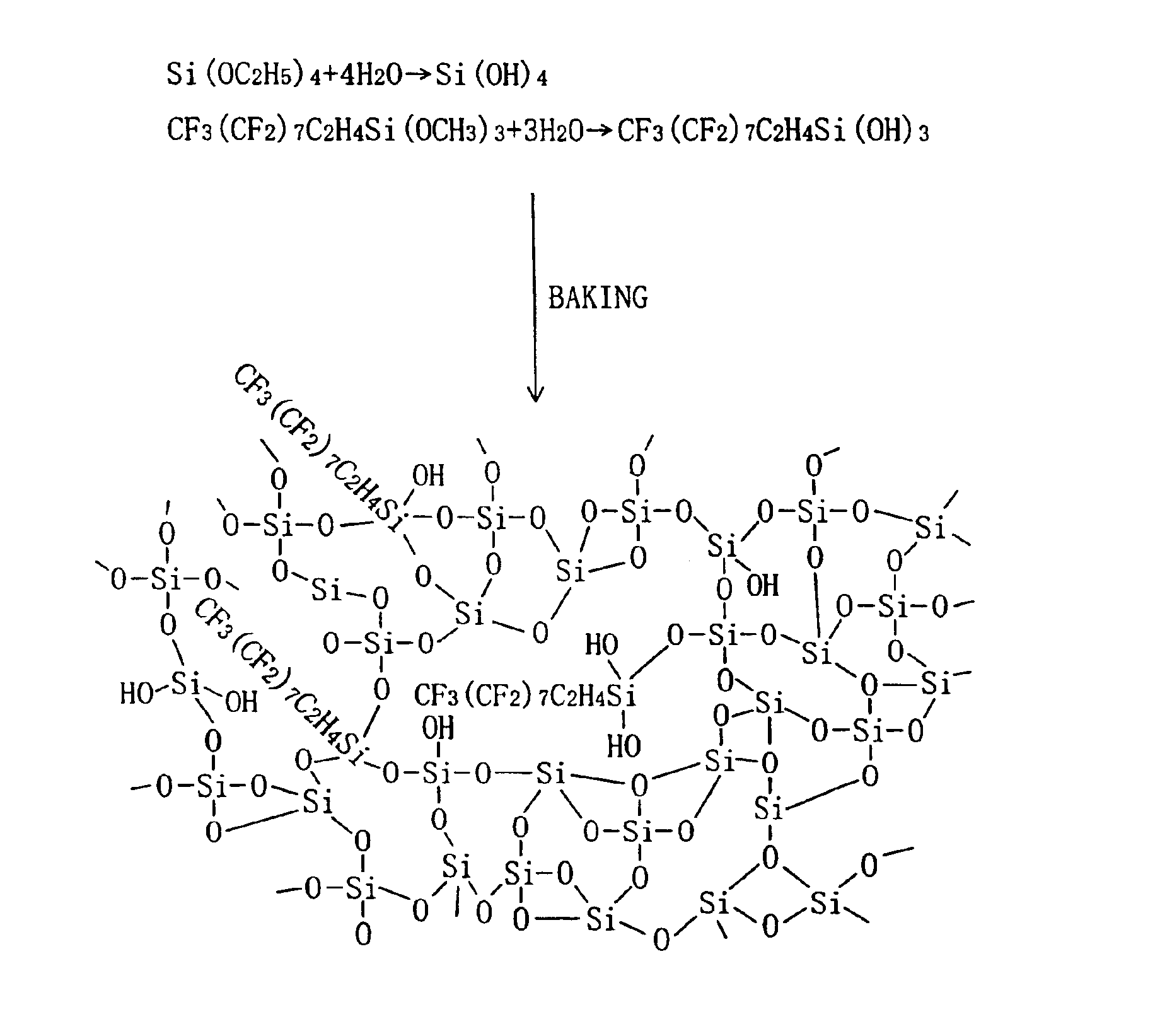
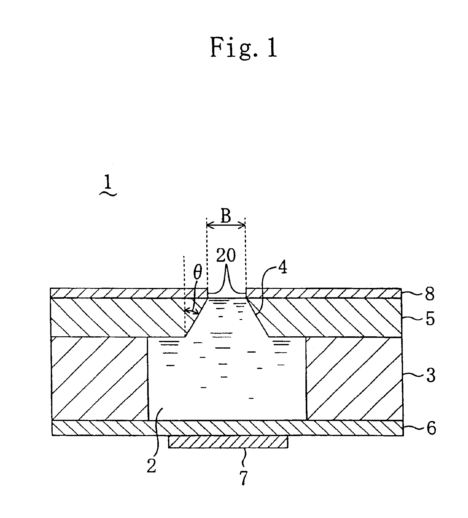
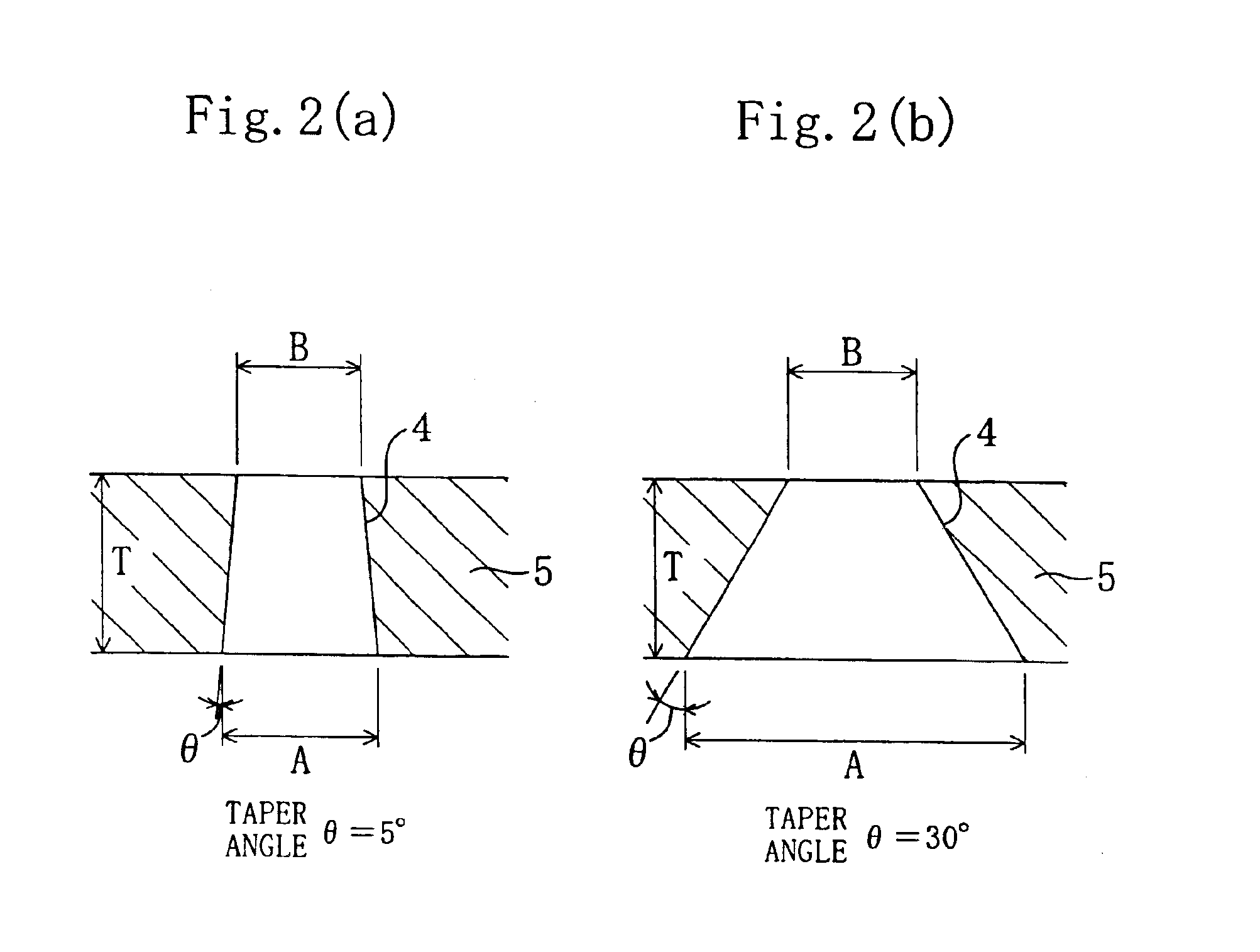
As FIG. 1 shows, in an ink jet head 1 in accordance with a first embodiment of the present invention, a nozzle plate 5, in which a nozzle orifice 4 is formed, is fixedly secured to the right side (the upper side in FIG. 1) of a head main body 3 which defines side walls of a pressure chamber 2. Fixedly secured to the opposite side (the lower side in FIG. 1) of the head main body 3 is an oscillation plate 6 which compartments, together with the head main body 3, the pressure chamber 2. Further, a piezoelectric element 7, formed of a film of PZT, is fixedly secured to the lower side of the oscillation plate 6. In addition, a water repellent thin film 8, which contains therein a molecule in which fluoroalkyl chains are bonded to or dispersed in silicon oxide, is formed overlying the ink jetting side (the upper side in FIG. 1) of the nozzle plate 5.

It is preferred that the film thickness of the water repellent thin film 8 ranges from 10 nm up to 1000 nm, more preferably, from 100 nm up t...

embodiment 2

As schematically shown in FIG. 4, an ink jet head according to a second embodiment of the present invention is formed such that the density of a molecule 14 as a water repellent molecule having a fluoroalkyl chain in the water repellent thin film 8 is thicker at the side of an upper surface 11 (i.e., the jetting side) than at the side of an interface 10 with the nozzle plate 5 (i.e., the base material 9).

Since the water repellent molecule 14 is generally low in compatibility with a silica network 15, the density of the water repellent molecule 14 has a tendency of thickening toward interfaces on either side of the water repellent thin film 8 (i.e., toward the upper surface 11 and toward the interface 10 on the base material's 9 side). So, if the water repellent molecule 14 is thick in density at the side of the upper surface 11 of the water repellent thin film 8, this provides the advantage that the water repellency of the upper surface 11 is enhanced. However, conversely, if the de...


PUM

PropertyMeasurementUnit
thicknessaaaaaaaaaa
thicknessaaaaaaaaaa
thicknessaaaaaaaaaa

Abstract

A coat liquid, in which a methoxysilane or ethoxysilane compound which is a precursor of silicon oxide and an ethoxysilane or methoxysilane compound which contains therein a carbon fluoride chain are dissolved, is applied onto the surface of a base material of SUS having a thickness of 20 μm. This is followed by drying the base material for one hour at room temperature condition. Thereafter, the base material is baked at 200 degrees centigrade for 30 minutes thereby to form a water repellent thin film having a thickness of from 10 nm to 1000 nm and containing therein a molecule in which fluoroalkyl chains are bonded to the silicon oxide. A nozzle orifice is formed by electrical discharge machining from the lower side of the base material.

Description

FIELD OF THE INVENTIONThe present invention relates to an ink jet head, and to a method for the manufacture thereof. More specifically, the present invention relates to an ink jet head comprising a nozzle member on which surface a thin film having water repellency has been formed, and to a method for the manufacture of such an ink jet head.BACKGROUND OF THE INVENTIONWith the recent improvement in operation speed and image quality, and the reduction in production cost of recording devices such as a printer, a word-processing machine, a facsimile machine, or the like, many of the recording devices employ an ink jet recording method. Typically, the ink jet head employed in such an ink jet recording device has nozzles from which ink droplets are jetted toward a recording medium such as a sheet of paper on which these ink droplets land to effect printing.Incidentally, if water repellency at a portion surrounding a nozzle orifice of the nozzle member is insufficient, this will cause the i...

Claims


Application Information

Patent Timeline
Patent Type & Authority Patents(United States)
IPC IPC(8): B41J2/16B41J2/135
CPCB41J2/1606B41J2/161B41J2/1645B41J2/1634B41J2/1632
Inventor TOMITA, KENJINAKAGAWA, TOHRUSOGA, MAMORUSHIMAMOTO, KEISUKE
Owner PANASONIC CORP
Features
  • R&D
  • Intellectual Property
  • Life Sciences
  • Materials
  • Tech Scout
  • Unparalleled Data Quality
  • Higher Quality Content
  • 60% Fewer Hallucinations
Learn More