Ejector sleeve for molding a raised aperture in a molded article

a technology of ejector sleeves and raised apertures, which is applied in the field of injection mold can solve the problems of damage, mold jamming, and core pins and sleeves that can be broken or bent during installation, and achieve cost savings, thin side walls, and reduced costs

Inactive Publication Date: 2005-03-29
PROGRESSIVE COMPONENTS INT CORP
View PDF7 Cites 35 Cited by
  • Summary
  • Abstract
  • Description
  • Claims
  • Application Information

AI Technical Summary

Benefits of technology

The present invention includes an improved ejector sleeve having thinner side-walls than prior sleeves. The sleeves generally include a ring for mounting the sleeve, a central bore for receiving a core pin, a tube portion extending from the ring to a tube end portion. The side-walls defining the tube end portion have a thickness of less than forty thousandths, and preferably thirty thousandths of an inch. These thinner side-walls allow the end user to manufacture molded articles with raised apertures having the same interior diameter and thinner aperture side-walls. This results in decreased costs due to reduced mold cycle times as well as cost savings due to material reduction.
In one preferred aspect of the invention, a coated ejector sleeve is provided in which a thin, lubricous coating of nickel, chromium or alloys of chromium or nickel is applied to at least a portion of the sleeve. A similar coating is also preferably applied to the pin. The coating is applied in thickness of less than 0.0001 inch which improves the wear characteristics of the pins and sleeves as well as allowing the coated pins and sleeves to be stocked and used as nominal thickness parts. Such coated pins and sleeves have demonstrated improved wear resistance as well as lesser susceptibility to failure during operation in a mold.
In one embodiment of the invention, a sleeve extension is provided which has a base portion adapted to mount to an ejector plate. The sleeve extension preferably has a T-slot on the end opposite the base for receiving amounting base of an ejection sleeve. The sleeve extension includes a through bore dimensioned to receive a core pin. The sleeve extension provides structural support for long, thin walled sleeves thereby allowing the use of longer stock ejector sleeves with decreased side-wall thickness.
In another embodiment of the invention, an improved core element mounting system is provided which allows for greatly simplified installation of a floating core mount. The mounting system of the invention provides sufficient head clearance that the core pin and sleeve adjust or deflect away from the sides of the mold without breaking. The system utilizes a novel plug which includes a threaded exterior surface, a plug shoulder for engaging a stop surface of a bore formed in the mold, a driving surface for engagement with a driving tool, and a head contacting surface for supporting the head of the core pin. The mounting system can be installed in a single aperture which can be machined in three steps. These steps may include machining a core element bore, machining wider bore which is dimensional to receive and engage the plug body and to have sufficient depth to accommodate the core pin head and provide head clearance, and machining a still wider bore which is dimensioned to receive the shoulders of the plug.

Problems solved by technology

Given the long, slender shape of the pin and sleeve, the core pin and sleeve can become broken or bent during installation or during the molding cycle.
This damage may occur when the sleeve or molded article catch upon the sides of the aperture or are not properly positioned when the mold is closed.
When the pin or ejector sleeve are damaged, the mold may become jammed and the mold machine must be taken off-line, disassembled and repaired.
These repairs increase the maintenance costs for the injection mold machine and cause the mold's end user to lose valuable production time.
Another problem with prior core pins and sleeves is that when the molded article is ejected from the mold, the walls of the hole formed in the article can suffer fracture or defect due to adhesion of uncured plastic to the mold, core pin or sleeve.
This damage can be due to the side walls having insufficient time to cure or cool during the mold cycle.
Even a small increase in cycle time per piece can become a significant manufacturing cost when considering the number of articles being produced.
However, mold component manufacturers have been reluctant to provide thinner sleeves due to their perceived fragility, particularly when the end user wants a sleeve of considerable length, e.g. a sleeve that is more than four inches long.
This results in the mounting shoulder of the core pin being held tight against the interior surface of the press piece.
Such a rigid hold on the base of the pin does not allow for any movement of the pin or sleeve relative to the molded part which can cause the pin and / or sleeve to be damaged during ejection of the part.
However, this type of plate mount suffers from several drawbacks.
This process adds several additional machining steps to the design and manufacture of the injection mold thereby increasing the mold's production cost.
Further, since useable space for fitting required components on a mold is usually limited, the floating mount plate is often viewed as an inefficient use of that available space on the mold.
Another problem with prior ejector sleeves was that they become worn quicker than is desirable by friction between the exterior surface of the sleeve and the mold base as well as between the interior surface of the sleeve and the exterior surface of the core pin.

Method used


Image

  • Ejector sleeve for molding a raised aperture in a molded article
  • Ejector sleeve for molding a raised aperture in a molded article
  • Ejector sleeve for molding a raised aperture in a molded article

Examples


Embodiment Construction

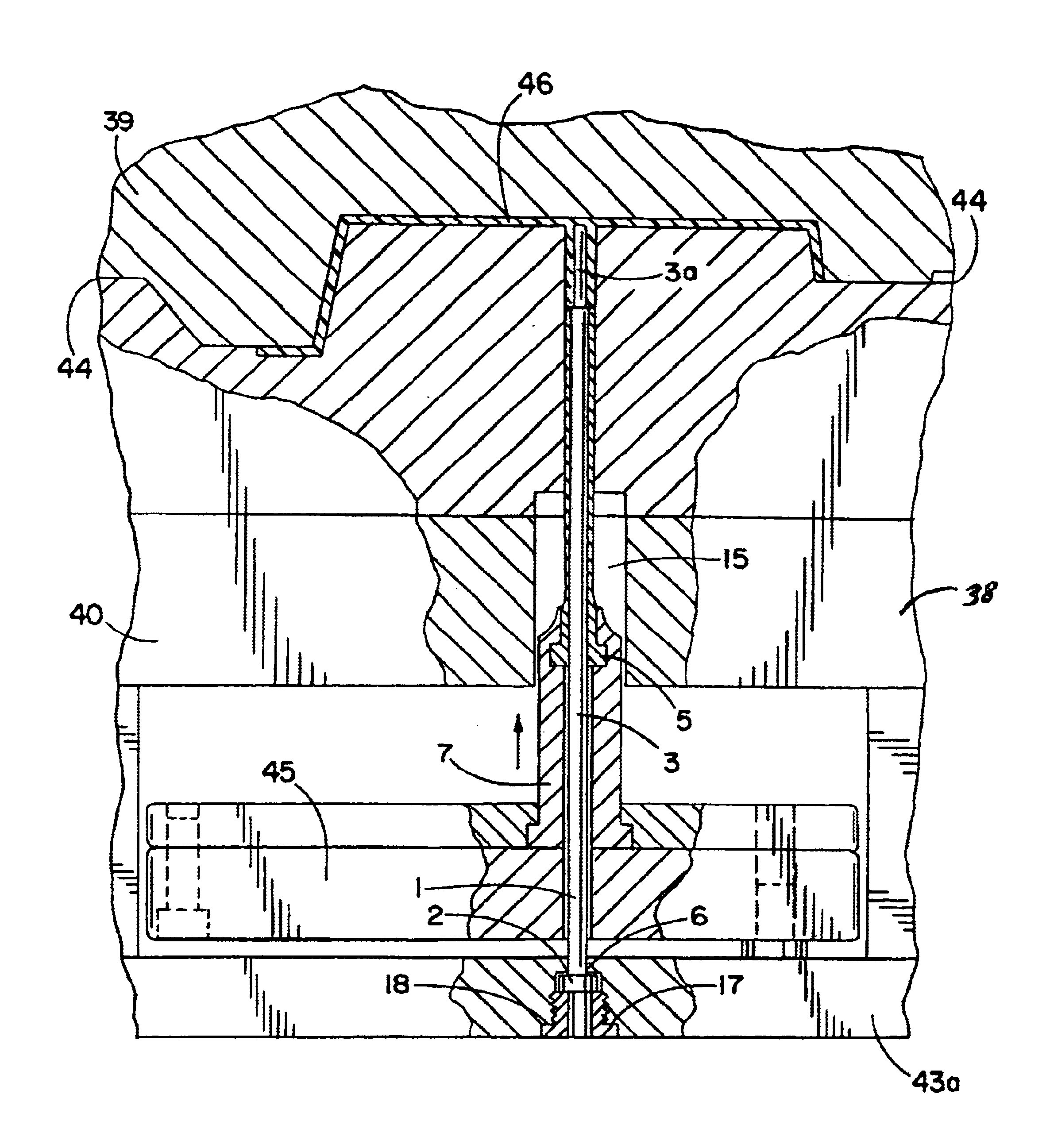
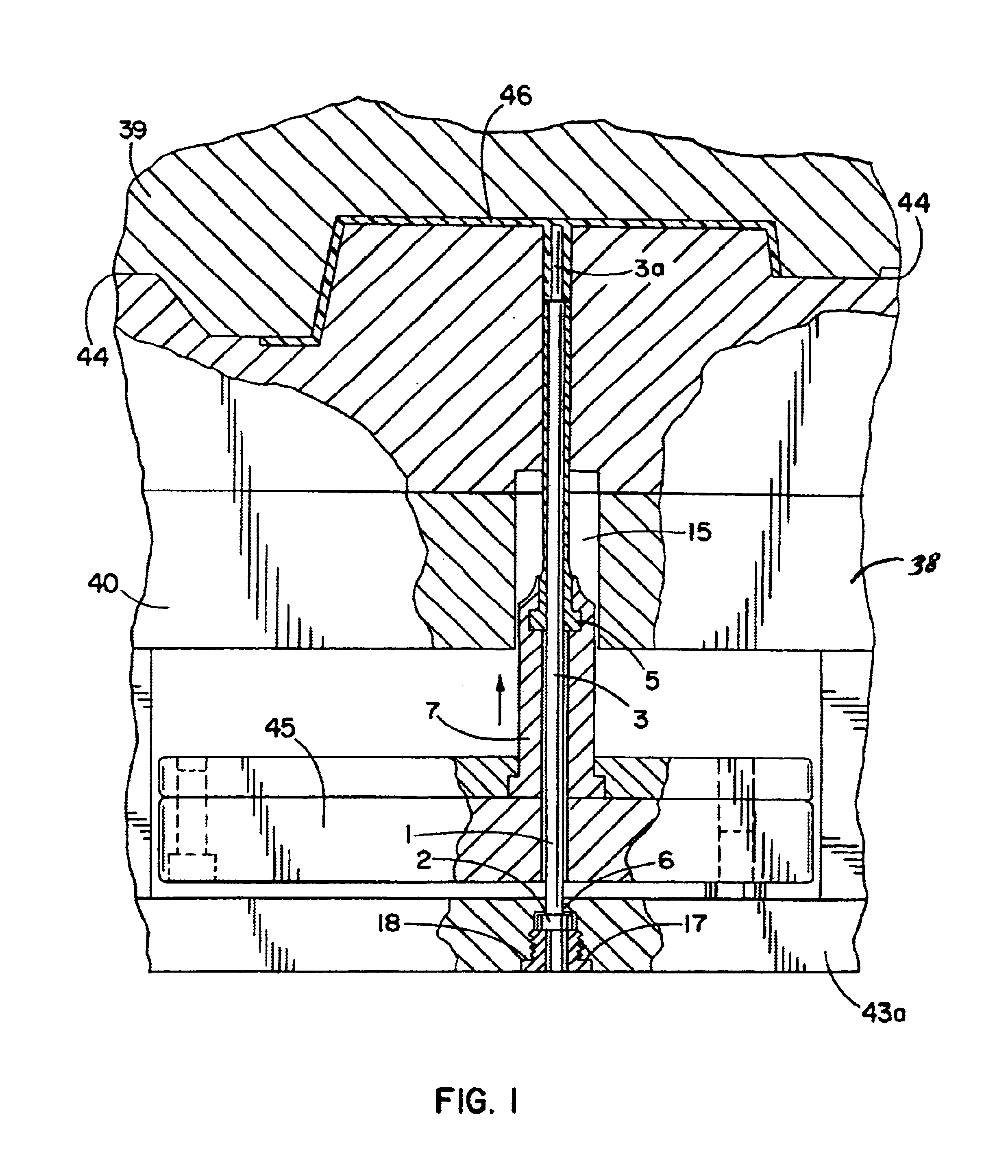
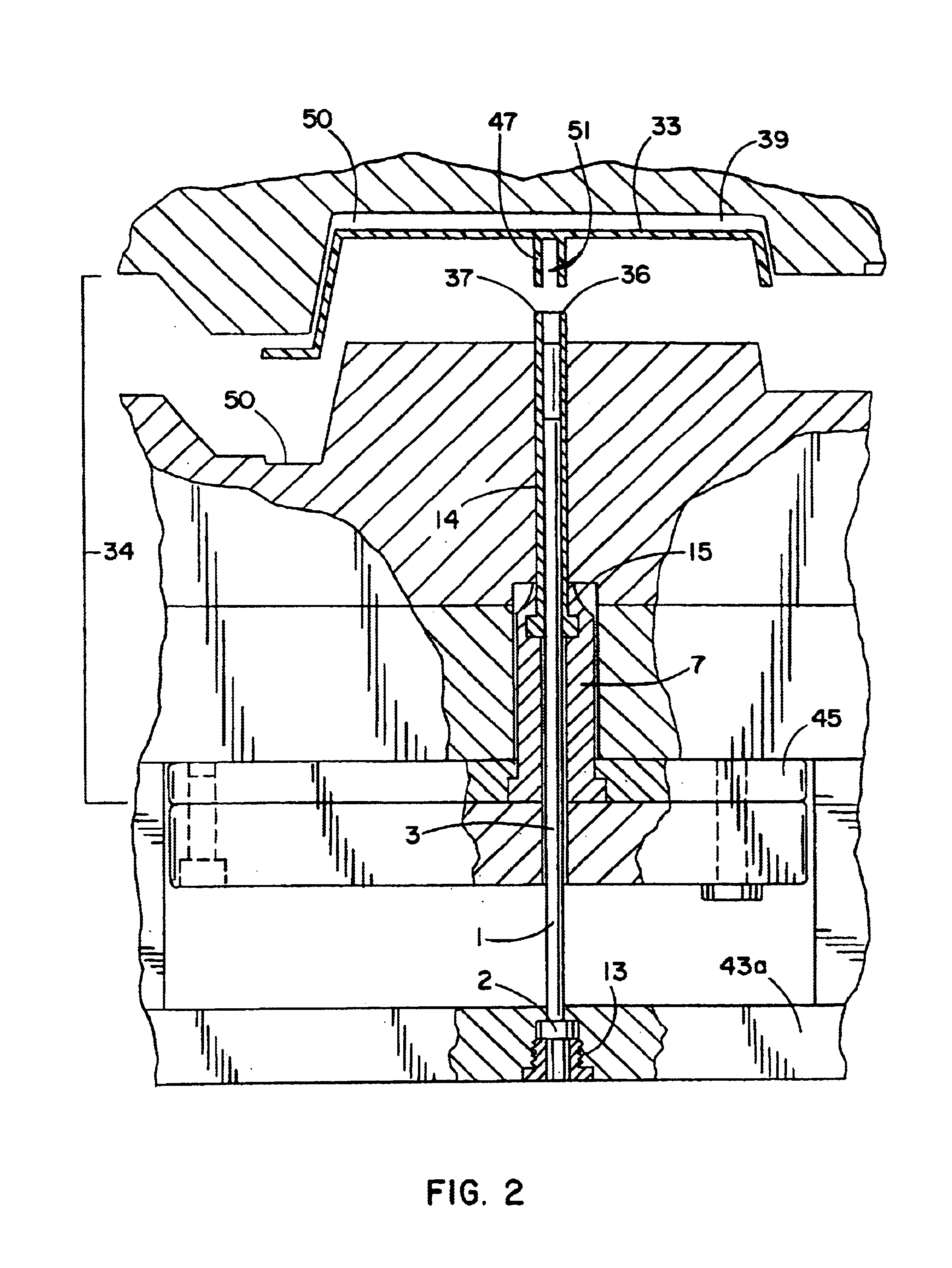
The thin wall sleeves of one embodiment of the invention are shown mounted to an injection mold in FIGS. 1 and 2. As can be seen with referenced to these figures, core pin 1 extends through ejector plate 45, ejector sleeve extension 7 and ejector sleeve 5. The assembly of these pieces is best depicted in FIG. 3, which is an exploded view of these pieces. Ejector sleeve 5 is mounted through the T-slot 4 provided in the side of ejector sleeve extension 7. The core pin 1 is threaded through ejector sleeve extension 7 and ejector sleeve 5 and held in place by the mounting plug 9. As depicted in FIG. 3, the core pin 1 has a pin head 2, a shaft 3 having a first diameter and, as shown, may have a shaft end 3a which is machined by the end user to have a smaller diameter than the diameter of the shaft 3. The change in diameter between the pinhead 2 and shaft end 3a forms a pin shoulder 22 around the exterior surface of the pin 1.

As can be seen in FIGS. 1 and 2, the mold 38 including cavity h...


PUM

PropertyMeasurementUnit
thicknessaaaaaaaaaa
thicknessaaaaaaaaaa
thicknessaaaaaaaaaa

Abstract

The present invention includes an improved ejector sleeve (5) having thinner side-walls than prior sleeves. The sleeves generally include a ring (31) for mounting the sleeve, a central bore (42) for receiving a core pin (1), a tube portion extending from the ring to a tube end portion. The side-walls defining the tube end portion have a thickness of less than forty thousandths, and preferably thirty thousandths of an inch. Preferably, the coated ejector sleeve is provided in which a thin, lubricous coating of nickel, chromium or alloys of chromium or nickel is applied to at least a portion of the sleeve. The coating is applied in thickness of less than 0.0001 inch which improves the wear characteristics of the pins and sleeves as well as allowing the coated pins and sleeves to be stocked and used as nominal thickness parts.

Description

FIELD OF THE INVENTIONThe invention generally relates to injection mold core pins and sleeves, which are used to form cored holes in articles formed by injection molding. More particularly, the invention relates to a core pin system including an improved thin walled sleeve, which preferably is used with an improved core pin retainer.BACKGROUNDIn injection molding, upper and lower mold halves are brought together to define a mold cavity into which heated molten plastic is injected under pressure. The mold halves are typically vertically aligned with an upper mold portion termed the cavity half and a lower mold portion termed the core mold half. For forming holes or apertures through the top or bottom surfaces of molded pieces, coring elements, such core pins are frequently utilized. When a raised aperture having side walls extending from the surface of the molded part is desired, the core element is often provided with an associated ejector sleeve which assists in forming a lip of th...

Claims


Application Information

Patent Timeline
Patent Type & Authority Patents(United States)
IPC IPC(8): B29C45/40B29C45/26
CPCB29C45/401B29C45/4005B29C45/2628
Inventor STARKEY, GLENN
Owner PROGRESSIVE COMPONENTS INT CORP
Why Eureka
Try Eureka