Double-y-shaped multi-lumen catheter with selectively attachable hubs

a multi-lumen catheter and hub technology, applied in the field of medical devices, can solve the problems of inability to optimally place the catheter tip, lack of dialysis treatment effect, and lack of optimal placement of the catheter tip of the double lumen catheter

Inactive Publication Date: 2005-03-29
ARROW INT INC
View PDF67 Cites 217 Cited by
  • Summary
  • Abstract
  • Description
  • Claims
  • Application Information

AI Technical Summary

Benefits of technology

A method for surgically implanting a double-Y-shaped multi-lumen catheter into a patient is also provided. The method is suited for implanting a multi-lumen catheter having an elongated, central, multi-lumen tube portion, a proximal end portion including a single-lumen proximal veinal extension tube and a single-lumen proximal arterial extension tube each having a proximal tip, and a distal end portion including a single-lumen distal veinal extension tube and a single-lumen distal arterial extension tube each having a distal end. The method includes making an incision in the skin of the patient, and inserting the proximal tips of the proximal veinal and arterial extension tubes through the incision and placing the proximal tips in the patient. A subcutaneous tunnel is formed having a first end proximate to the incision and second end remote from the first end of

Problems solved by technology

Both types, however, present certain deficiencies.
While double lumen catheters (e.g., U.S. Pat. No. 4,895,561) allow for a single insertion of the catheter into the desired vein, double lumen catheters typically do not permit optimal catheter tip placement.
Non-optimal tip position may significantly lower flow values, resulting in less effective dialysis treatment.
The estimated catheter tube length and subsequent forward tunneling may result in less than optimal tip placement.
Deficiencies, however, exist in this method of catheterization as well.
One problem associated with this method is that this method requires two separate venous insertions, namely, two tunnels and two of each accessory instrument used for the procedure.
Whi

Method used


Image

  • Double-y-shaped multi-lumen catheter with selectively attachable hubs
  • Double-y-shaped multi-lumen catheter with selectively attachable hubs
  • Double-y-shaped multi-lumen catheter with selectively attachable hubs

Examples


Embodiment Construction

For the purposes of the following description and the claims appended hereto, the relative term “proximal” refers to those portions of a catheter and those portions of components of the catheter which are nearest the insertion end of the catheter, that is, the end of the catheter that is inserted into an area of a patient'as body being catheterized, such as a blood vessel. Conversely, the relative term “distal” refers to those portions of a catheter and those portions of components of the catheter which are farthest from the insertion end of the catheter.

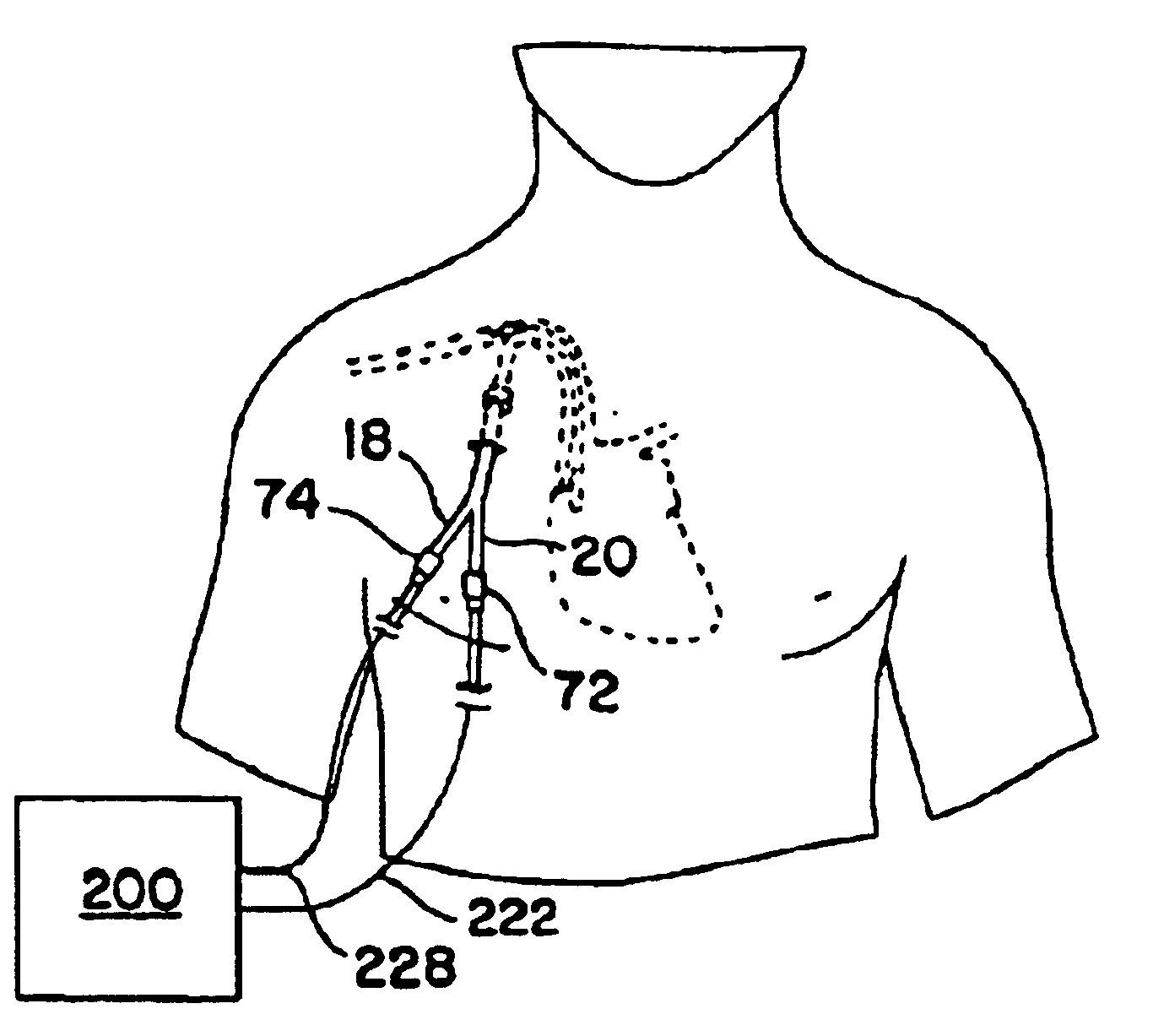
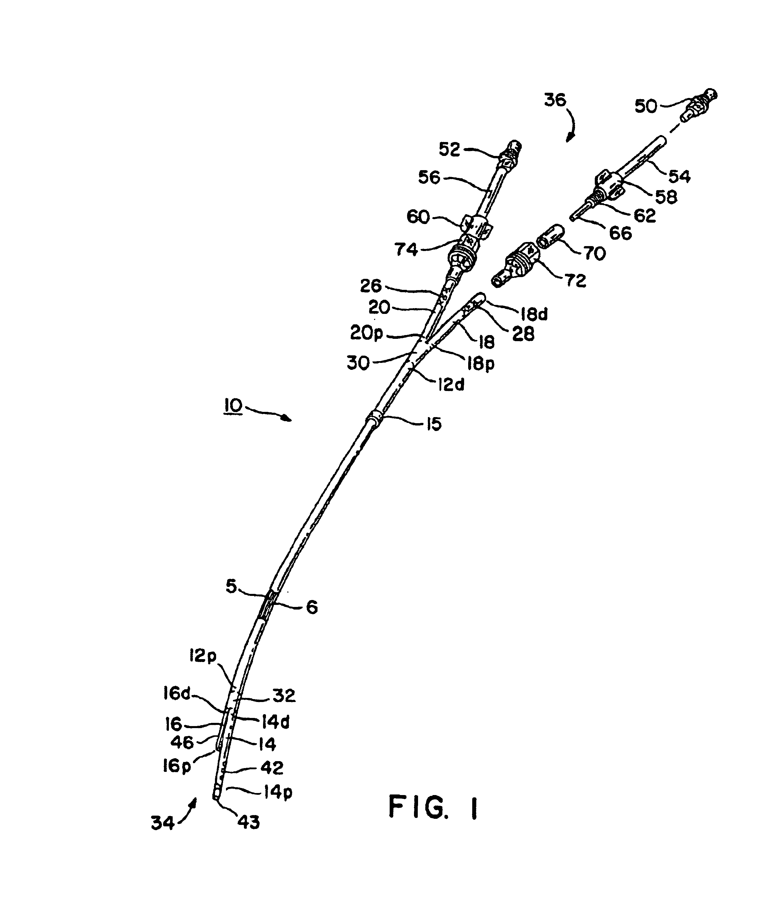
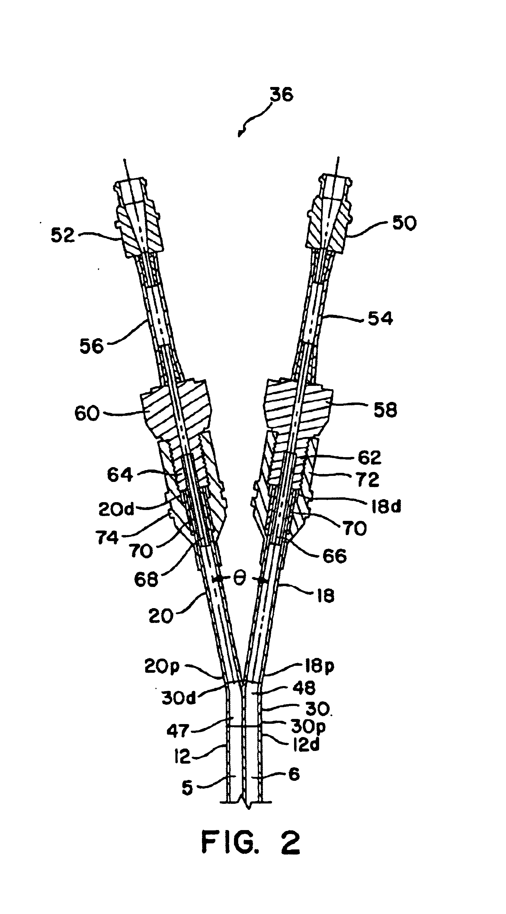
FIG. 1 shows a double-Y-shaped multi-lumen catheter 10 according to the present invention. The catheter 10 includes a proximal end 34 for insertion into a patient, and a distal end 36 for connection to a fluid exchange device, such as a dialysis machine or the like. The catheter 10 includes an elongated, central, multi-lumen tube portion 12, a plurality of proximal single-lumen extension tubes 14, 16, and a plurality of distal singl...


PUM


Abstract

A multi-lumen catheter and method for inserting same in a patient is disclosed. The catheter includes an elongated, central, multi-lumen tube portion having a proximal end and a distal end. The central tube portion has a substantially cylindrical outer shape and is internally segmented into a plurality of lumens. A distal branch portion includes a plurality of single-lumen distal extension tubes. A proximal branch portion includes a plurality of single-lumen proximal extension tubes. Each proximal extension tube has a distal first end and a proximal second end. The distal first end of each proximal extension tube is connected to the proximal end of the central tube portion such that the single lumen of each distal extension tube is in fluid communication with one of the plurality of lumens of the central tube portion. Each lumen of the central tube portion and the lumens of the distal and proximal extension tubes in fluid communication therewith define a flow path through the catheter. Selectively attachable hub connectors are provided for selective attachment to the distal extension tubes and connection of the catheter to a fluid exchange device.

Description

BACKGROUND1. Field of the InventionThe present invention relates generally to medical instruments and more specifically to a multi-lumen catheter including y-shaped distal and proximal ends, and including selectively attachable hubs for selectively connecting the catheter to a fluid exchange device.2. Description of the Prior ArtCatheters, generally, are hollow, flexible tubes for insertion into a body cavity, duct, or vessel to allow the passage of fluids or distend a passageway. Catheters are often used for temporary or long-term dialysis treatment. Dialysis treatment provides for blood to be withdrawn from the patient, purified, and then returned to the patient. Thus, in dialysis treatment, catheters are used to allow passage of a patient's blood into and out of the patient's body. For optimal performance during dialysis treatment, the catheter tips, both in-flow and out-flow, should be placed in close proximity to the heart. Typically, medical personnel use either a double lumen...

Claims


Application Information

Patent Timeline
IPC IPC(8): A61M1/36A61M25/00A61M1/16A61M3/00A61M25/14
CPCA61M1/3653A61M25/0029A61M25/0097A61M1/3659A61M1/16A61M2025/0034A61M2025/0037A61M2025/0098A61M2025/0031A61M1/3661
Inventor WILSON, JON S.FLEMING, CARL M.CASSIDY, KENNETH T.BOYD, RONALD D.FLEMING, GARY S.
Owner ARROW INT INC
Why Eureka
Try Eureka