High speed carbon dioxide gas welding method

Inactive Publication Date: 2005-03-29
YASKAWA DENKI KK
View PDF5 Cites 26 Cited by
  • Summary
  • Abstract
  • Description
  • Claims
  • Application Information

AI Technical Summary

Benefits of technology

A seventh aspect of the present invention provides a high-speed carbon dioxide gas welding method as set forth in any

Problems solved by technology

As a result, arcing stability is lost and spatters frequently occur.
Furthermore, a problem exists such that, when effects of arc pressure become strong, namely, when a large current occurs, the gauging region is expanded, and finally, solidification proceeds before the region has been sufficiently buried by the exposed portion, whereby undercuts of humping beads are produced.
As in the above, according to the prior art, in high-speed carbon dioxide gas welding at a rate of approximately 1.5 m / minute or more, employment of a buried arc method with a shortened arc length can suppress occurrence of large-sized spatters to some extent, whereas the arc heat source is buried inside the surface of the base metal, resulting in deep penetration.

Method used


Image

  • High speed carbon dioxide gas welding method
  • High speed carbon dioxide gas welding method
  • High speed carbon dioxide gas welding method

Examples


first embodiment

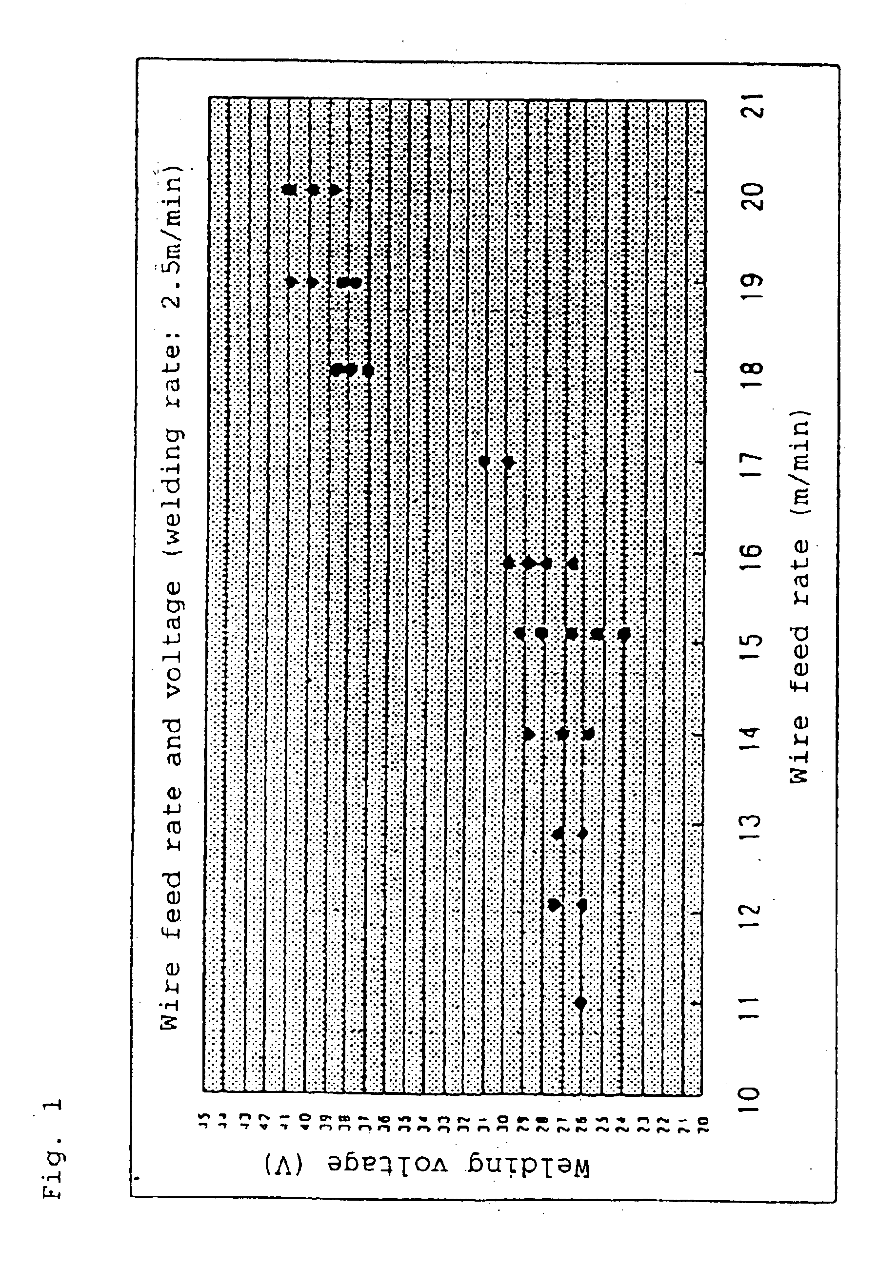
Hereinafter, a mode for carrying out the present invention will be described in detail based on a first embodiment shown in the drawings. FIG. 4 is a high-speed gas welding region expressed by the welding wire feed rate and welding voltage with a welding rate of 2.5 m / minute in the present invention.

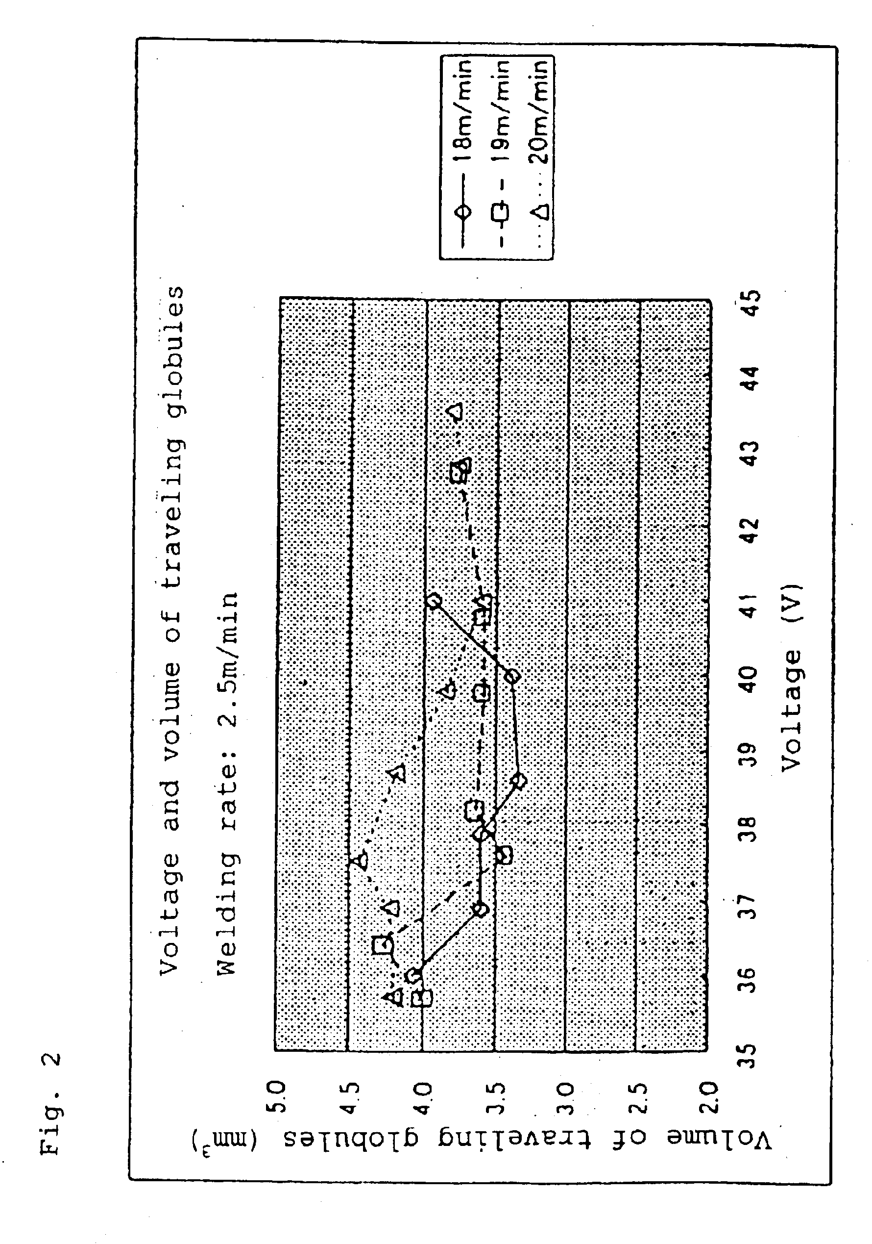
FIG. 2 is a diagram showing a relationship between the welding voltage and volume of traveling globules with a welding rate of 2.5 m / minute according to the present invention.

FIG. 3 is a diagram showing a relationship between the welding voltage and traveling period of globules with a welding rate of 2.5 m / minute according to the present invention.

FIG. 4 is a diagram showing a welding region of the present invention, a buried arc region, a humping region, and a breaking region with a welding rate of 2.5 m / minute.

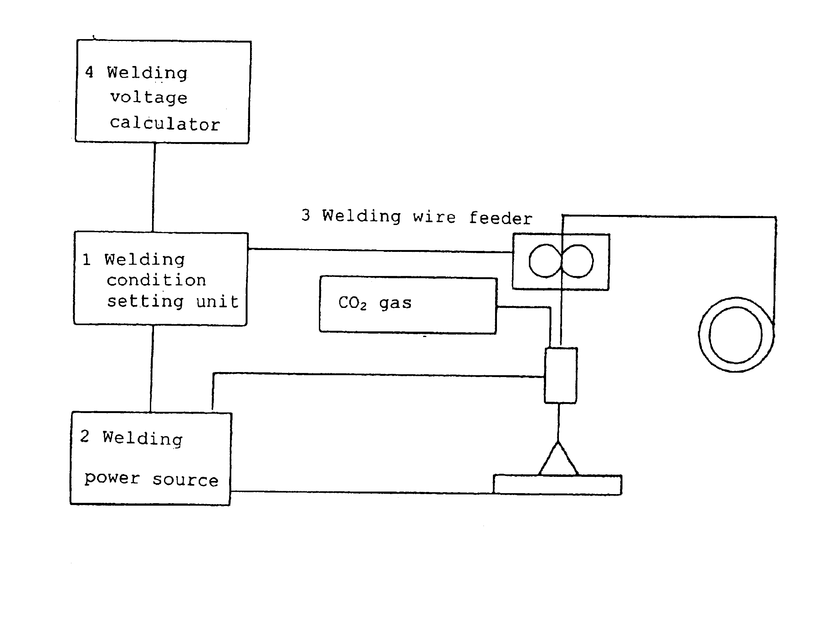
FIG. 5 is welding equipment for carrying out the method according to the present invention, wherein 1 denotes a welding condition setting unit, 2 denotes a power source having a ...

fifth embodiment

Now, a fifth embodiment will be described. First, traveling of globules according to the present embodiment will be described. As shown in FIG. 3, the period where globules depart from the front end of a welding wire and travel to a base metal (hereinafter, referred to as a traveling period of globules) is nearly fixed. In addition, as shown in FIG. 2, the volume of globules which depart from the front end of a welding wire and travel to a base metal (hereinafter, referred to as a volume of traveling globules) is nearly fixed. FIG. 6 are waveforms of a welding current and a welding voltage in welding according to the present invention, wherein virtually no short circuit has occurred. In short, globules formed at the front end of the welding wire are not short-circuited to the base metal and travel as shown in FIG. 7 in a nearly fixed period, indicating that stable welding has been carried out.

Where the volume of globules is provided as w(mm3), the traveling period of globules is pro...


PUM

PropertyMeasurementUnit
Lengthaaaaaaaaaa
Volumeaaaaaaaaaa
Speedaaaaaaaaaa

Abstract

An arc welding method which suppresses sputtering and which makes it possible to obtain a smooth bead penetration surface shape as in MIG or MAG welding, without producing undercuts or bumping beads. A carbon dioxide gas welding method effecting welding at welding rates of about not less than 1.5 m / minute using a consumable electrode and a welding power source having a control means for opening a short circuit at a rate of at least about 500 A / msec on detection of such short circuit, wherein welding is effected with a proper volume of globules under the welding conditions obtained by computing a welding voltage corresponding to the proper volume of globules by a first formula representing the relationship between the welding wire feed rate, the welding voltage and the volume of globules traveling to a pond of weld as the welding wire is melting and a second formula representing the relationship between the wire feed rate, the welding voltage, and the period of globules traveling to a pond of weld as the welding wire is melting.

Description

TECHNICAL FIELDThe present invention relates to a carbon dioxide gas arc welding method and, in particular, to a high-speed carbon dioxide gas arc welding method for high-speed welding at a rate of approximately 1.5 m / minute or more (in a region having a voltage higher than that of a buried arc region, a humping region, and a fusing region, traveling of globules occurs in a nearly fixed fashion involving virtually no short circuit) using a power source having a control means for opening a short circuit at a rate of at least approximately 500 A / msec based on detection of such a short circuit.BACKGROUND ARTIn carbon dioxide gas welding, a shielding gas is CO2 and since the electrical gradient plasma is a great, arcing tends to occur from a point with the shortest possible distance, thus such arcing points concentrate in the vicinity of the lower portion of globules. Consequently, current density of the arc column is heightened and arcing results in a firm slender shape. Because of the...

Claims


Application Information

Patent Timeline
IPC IPC(8): B23K9/10B23K9/173B23K9/073B23K9/095B23K9/12
CPCB23K9/1062
Inventor KOGA, YASUHIROOKUMURA, SHINJINAKASHIMA, HARUKIHANDA, HIROYUKIHIRAYAMA, TAKAHIDE
Owner YASKAWA DENKI KK
Why Eureka
Try Eureka