Light source, and a field emission cathode

a field emission cathode and light source technology, applied in the field of light source, can solve the problems of complicated control equipment, serious drawbacks, delay after, etc., and achieve the effects of high emission and uniform distribution of emitted electrons, simple and robust construction, and high emission and reliability

Inactive Publication Date: 2005-03-29
NANOLIGHT INT
View PDF12 Cites 23 Cited by
  • Summary
  • Abstract
  • Description
  • Claims
  • Application Information

AI Technical Summary

Benefits of technology

By the features in claims 1 and 34, further, a light source having a field emitting cathode of simple and robust construction is obtained.
By the features in claim 5, further, a light source having a large active light emitting surface is achieved. This efficient use of the surface renders it possible to achieve a light source having a high light emission in relation to the heat produced.
By the features in claims 21 and 47, further, a field emitting cathode of simple and robust construction is obtained.
By the features in claims 21 through 33 and claims 47 through 54 a field emitting cathode is obtained which further provides for a high emission and uniform distribution of emitted electrons, in particular through a cylindrical surface region surrounding the cathode. A cathode with low interference between the field emitting surfaces is also achieved.

Problems solved by technology

It has many advantages, but suffers from serious drawbacks.
For example, there is always a delay after the power has been turned on until it starts to operate giving full light.
It needs complicated control equipment, which requires space.
To obtain light with a source of this kind it is unfortunately necessary to use materials having negative environmental effects.
It is for example a big disadvantage that mercury has to be used in this type of light sources.
The cathodoluminescent lamps shown in the documents mentioned do not have optimal surfaces.
Also, there is no indication in the document how to produce the light source in a cost-efficient way.
A construction according to this document having one fiber will be inoperative if the fiber is broken.
Previously known field emission cathodes are often of a complicated and fragile construction, especially as concerns the mountings and the attachment of field emitting bodies.
It has been found in connection with cathodes including standard carbon fibers and a grid that the electrical fields acting between the cathode and a grid or an anode can cause individual fibers to get loose from their carrier if they are not safely secured thereto.
Once loose, the fibers will, in most cases, be attracted by the grid and cause a short circuit between the cathode and the grid, until it burns off after some time due to the resulting current through the fibres.

Method used


Image

  • Light source, and a field emission cathode
  • Light source, and a field emission cathode
  • Light source, and a field emission cathode

Examples


Embodiment Construction

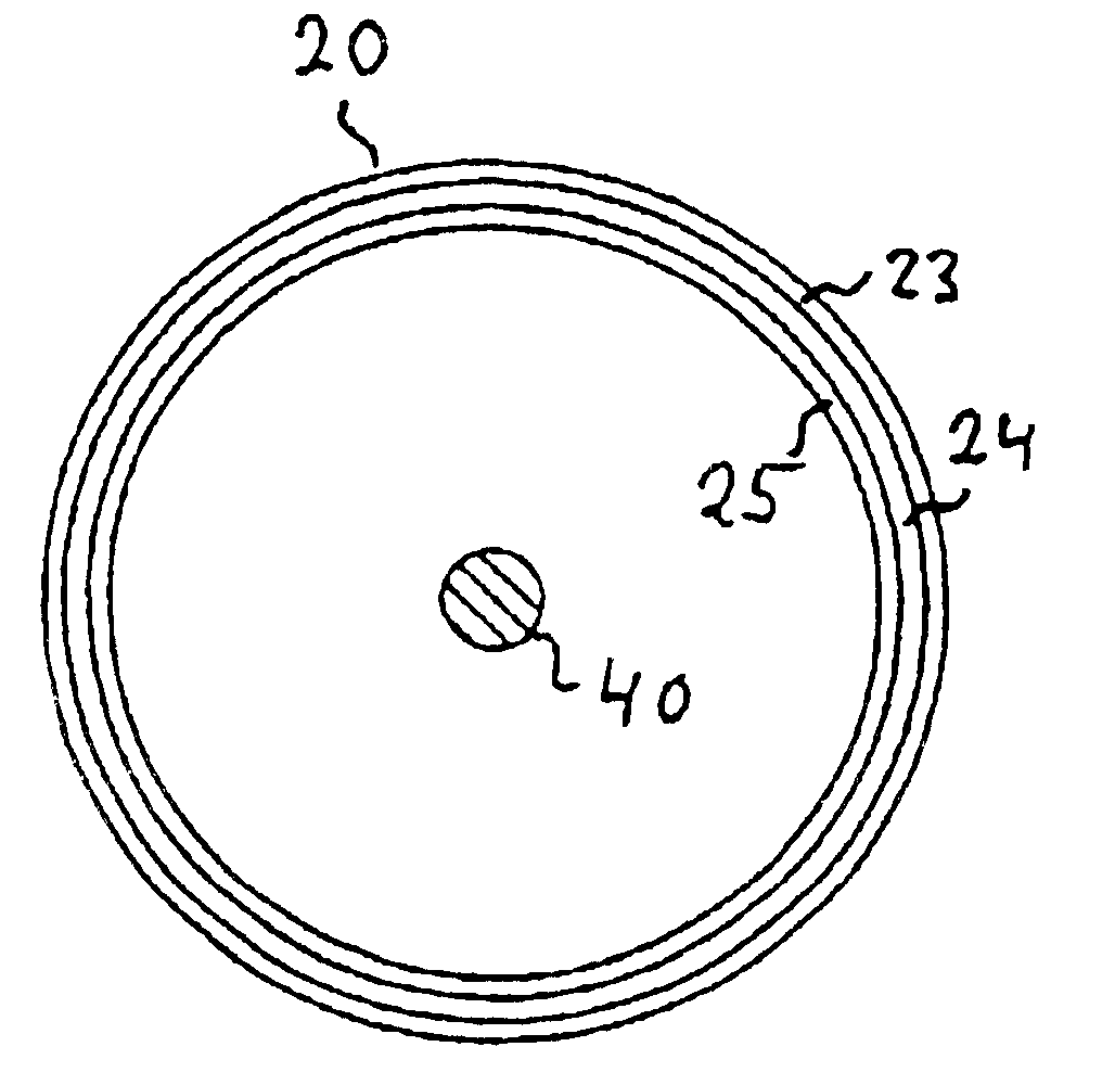
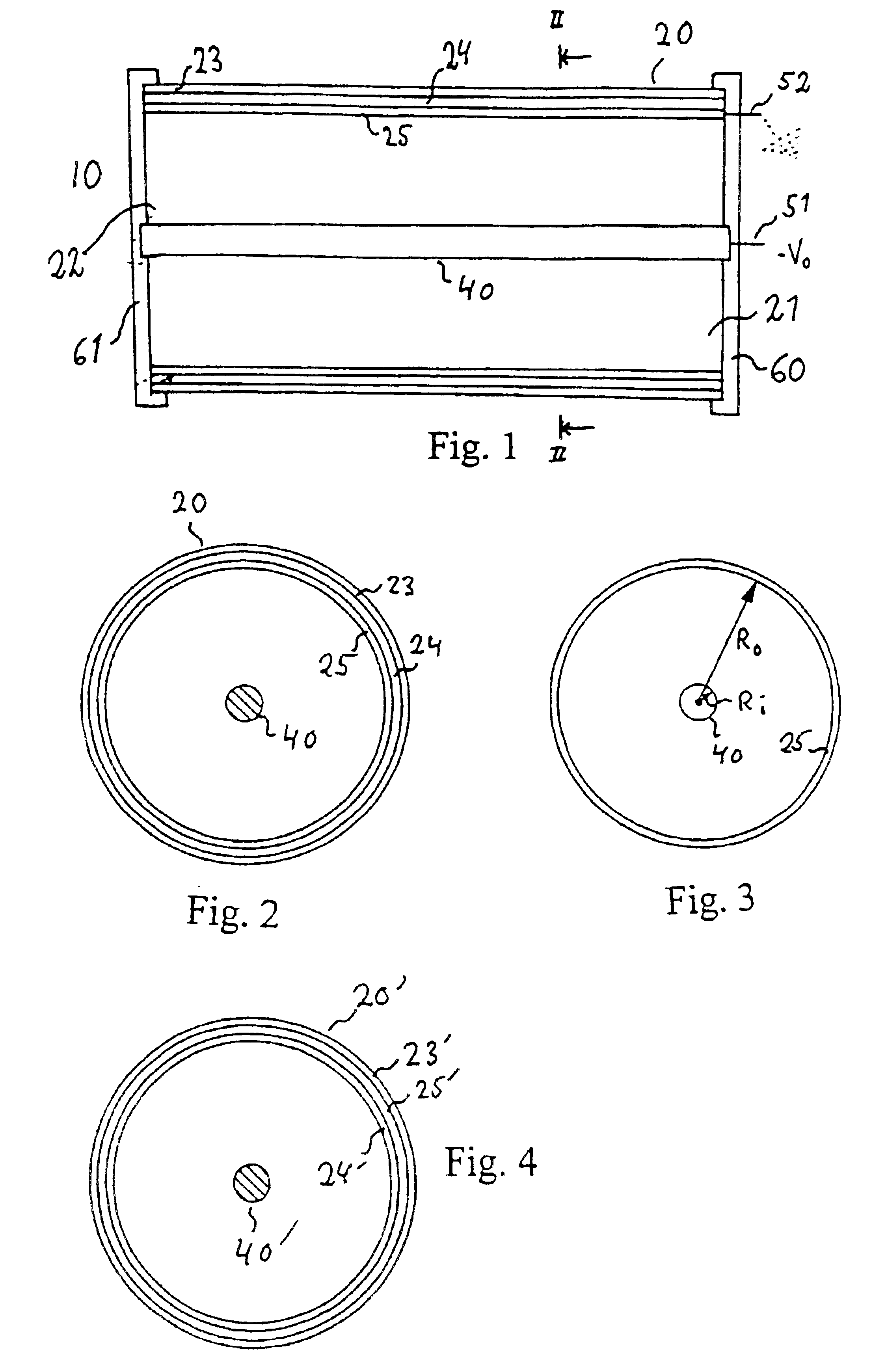
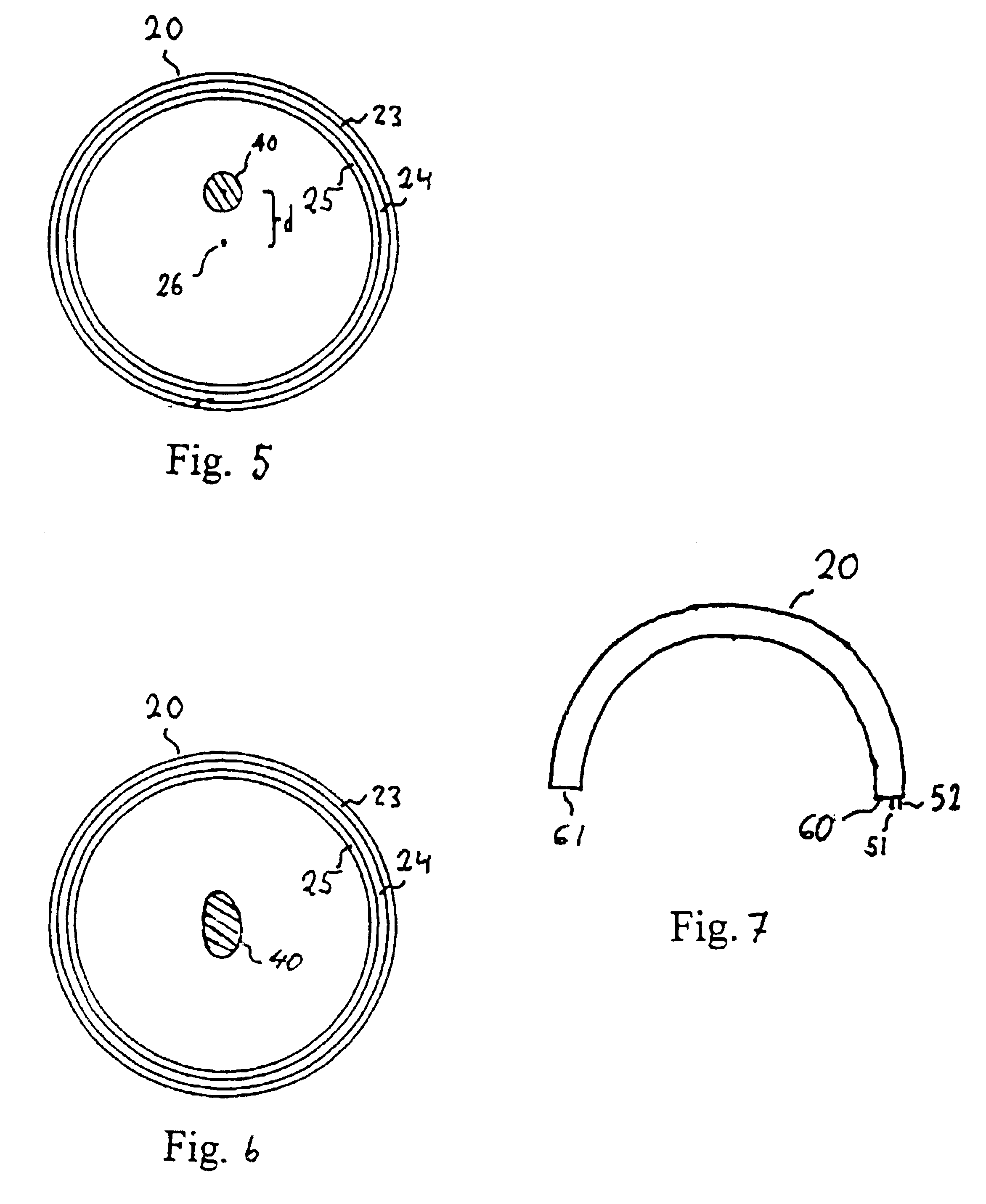
Referring to FIG. 1, there is shown, in a schematic longitudinal section, an embodiment of a light source according to the present invention, identified generally by the numeral 10, and especially intended for illumination purposes. It includes a container having walls, one of which is identified by the numeral 20. This wall 20 has an outer glass layer and is shown to be cylindrical. The cylinder 20 has an end 21, which is covered by an end cap 60. A sealing (not shown) is provided between the end cap and the cylinder 20, in order to achieve an airtight sealing of the container. At the other end 22 of the cylinder 20 an end cap 61 is provided, similar to the one arranged at the end 21, also provided with a sealing. Alternatively, at the end 22 there can be arranged a circular wall as a continuation of the cylinder wall 20, also having an outer layer of glass. The container is sealed in order to maintain the vacuum (approximately 10−6 torr) created when the container is evacuated.

Ins...


PUM


Abstract

The light source, comprises an evacuated container having walls, including an outer glass layer (23) which on at least part thereof is coated on the inside with a layer of phosphor (24) forming a luminescent layer and a conductive layer (25) forming an anode. The phosphor (24) is excited to luminescence by electron bombardment from a field emission cathode (40) located in the interior of the container. The field emission cathode (40) comprises a carrier having a diameter in the mm range. At least a portion of the surface of the carrier is provided with a conductive layer having surface irregularities in the form of tips, having a radial extension being less than about 10 μm. Due to the geometry and the tips, the electric field is concentrated and amplified at the field emission surface.

Description

FIELD OF THE INVENTIONThe present invention relates to a light source according to the introductory portion of claim 1, especially a light source for illumination. Further, the present invention relates to a field emission cathode according to the introductory portion of claim 21.BACKGROUND OF THE INVENTIONOne common type of light sources is the fluorescent tube. It has many advantages, but suffers from serious drawbacks. For example, there is always a delay after the power has been turned on until it starts to operate giving full light. It needs complicated control equipment, which requires space. To obtain light with a source of this kind it is unfortunately necessary to use materials having negative environmental effects. It is for example a big disadvantage that mercury has to be used in this type of light sources.Cathodolumninescent light sources is another interesting type of light sources. Such light sources, including an evacuated envelope containing a grid and a heated cath...

Claims


Application Information

Patent Timeline
Patent Type & Authority Patents(United States)
IPC IPC(8): H01J63/00H01J63/06H01J1/30H01J1/304
CPCB82Y10/00H01J1/3048H01J63/06Y10S977/95H01J2201/30469
Inventor KJELLMAN, JANLINDMARK, MAGNUS
Owner NANOLIGHT INT
Why Eureka
Try Eureka