Taper adjustment on reflector and sub-reflector using fluidic dielectrics

Active Publication Date: 2005-03-29
HARRIS CORP
View PDF6 Cites 9 Cited by
  • Summary
  • Abstract
  • Description
  • Claims
  • Application Information

AI Technical Summary

Benefits of technology

The invention concerns an antenna utilizing a reflector and/or sub-reflector which includes at least one cavity and the presence, absence or mixture of fluidic dielectric in the cavity. A pump or a composition processor, for example, can be used to add, remove, or mix the fluidic dielectric to the cavity in response to a control signal. A propagation delay or beam pattern or gain of a radiated signal through the antenna is selectively varied by manipulating the fluidic dielectric within the cavity.
The fluidic dielectric can be comprised of an industrial solvent. If higher permeability is desired, the industrial solvent can have a suspension of magnetic particles contained therein. The magnetic particles can be formed of a wide variety of materials including those selected from the group consisting of ferrite, metallic salts, and organo-metallic particles.
In accordance with a first embodiment of the present invention, a reflector antenna comprises a reflector unit having at least one cavity disposed on the reflector unit, at least one fluidic dielectric having a permittivity and a permeability, and at least one composition processor adapted for dynam

Problems solved by technology

Once the satellite transmission system is designed and launched, changing the beam patterns to improve the operational bandwidth would be difficult.
Additionally, antennas using feeds operating over a range of frequencies may also experience performance degradation due to appreciable side lobes in a given frequency range.
The diffraction spreads the radiation into unwanted directions and causes interference with other electronic systems.
Even fixed configurations may require adjustments over time for various reasons such as environmental conditions or normal wear and tear causing system degradation.
However, this approach is typically limited in applicability, as feed systems which would achieve the desired taper are often too large or are not physically practical.
The abrupt change can not be optimally removed with either of these two methods.
Without the ability to change beam patterns and coverage areas as well as to flexibly use multiple frequency ranges, additional satellites must be launched to provide the services to possible future subscribers, which increases the cost of delivering the services to existing custome

Method used


Image

  • Taper adjustment on reflector and sub-reflector using fluidic dielectrics
  • Taper adjustment on reflector and sub-reflector using fluidic dielectrics
  • Taper adjustment on reflector and sub-reflector using fluidic dielectrics

Examples


Example

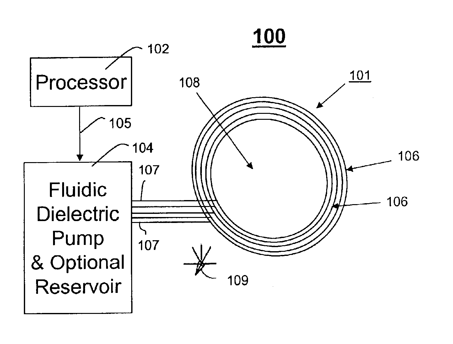
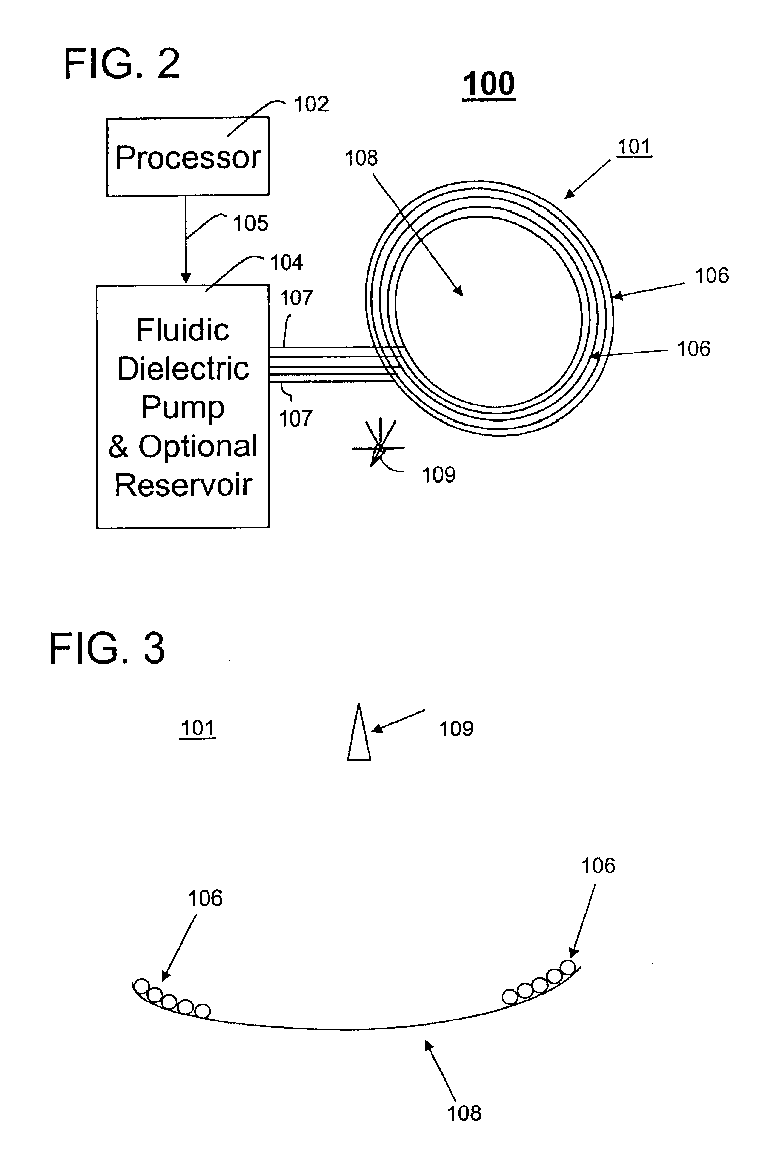
Although the antenna of FIG. 1 provides more flexibility than a conventional satellite reflector antenna, it is the ability to vary the dielectric value of a reflective element in the antenna of the present invention that enables it to be used in more than just a particular application or operating range without the complexities of a complete array of reflective elements. Reflectors and sub-reflectors in prior antennas all have static or fixed dielectric values. In contrast, the present invention utilizes a fluidic cavity or cavities as shall hereinafter be described in greater detail to provide even greater design flexibility for an antenna capable of further applications and wider operating ranges that further overcomes the detriments associated with side lobes.

Referring to FIGS. 2 and 3, a schematic diagram of an antenna system 100 using a reflector unit 101 having at least one cavity (and in this embodiment a plurality of cavities 106) that can contain at least one fluidic diele...


PUM


Abstract

A reflector antenna (100) includes a reflector unit (101) having at least one cavity (106) disposed on the reflector unit, at least one fluidic dielectric having a permittivity and a permeability, and at least one composition processor (104) adapted for dynamically changing a composition of the fluidic dielectric to vary at least the permittivity or permeability in at least one cavity. The antenna further comprises a controller (102) for controlling the composition processor to selectively vary at least one among the permittivity and the permeability in at least one of the cavities in response to a control signal.

Description

BACKGROUND OF THE INVENTION1. Statement of the Technical FieldThe present invention relates to the field of antennas, and more particularly to adjustable reflectors and sub-reflectors using fluidic dielectrics.2. Description of the Related ArtTypical satellite antenna systems use either parabolic reflectors or shaped reflectors to provide a specific beam coverage, or use a fiat reflector system with an array of reflective printed patches or dipoles on the flat surface. These “reflect array” reflectors used in antennas are designed such that the reflective patches or dipoles shape the beam much like a shaped reflector or parabolic reflector would, but are much easier to manufacture and package on a spacecraft. These antennas will be initially configured to reduce side lobes or to avoid reflecting side lobes.Since satellites typically are designed to provide a fixed satellite beam coverage for a given signal and may be limited in bandwidth by the structure of the reflectors such a con...

Claims


Application Information

Patent Timeline
IPC IPC(8): H01Q15/00H01Q15/14H01Q15/23H01Q19/02H01Q19/00
CPCH01Q15/148H01Q19/021H01Q15/23
Inventor RAWNICK, JAMES J.BROWN, STEPHEN B.
Owner HARRIS CORP
Why Eureka
Try Eureka