Liquid crystal display apparatus, driving method therefor, and display system

a technology of liquid crystal display and driving method, which is applied in the direction of electric digital data processing, instruments, computing, etc., can solve the problems of large number of external power sources, small power consumption of digital systems, and inability to adapt to portable displays

Inactive Publication Date: 2005-03-29
BOE TECH GRP CO LTD
View PDF36 Cites 97 Cited by
  • Summary
  • Abstract
  • Description
  • Claims
  • Application Information

AI Technical Summary

Benefits of technology

A liquid crystal display apparatus, a driving method therefor, and a display system according to the present invention are made to solve the foregoing drawback, and their object is to provide a high-image-quality liquid crystal display apparatus.

Problems solved by technology

Since the analog system consumes a large power in the circuit, it is not suited to a display for a portable computer.
In contrast, the digital system consumes a small power, but it requires that an output voltage be supplied from the outside and the number of external power sources becomes large.
Since the output voltage of a D / A converter is linear in general and its linearity differs from the g characteristic of liquid crystal, this system is not suited to gray-scale display.
A conventional TFT circuit, however, has the following drawback.

Method used


Image

  • Liquid crystal display apparatus, driving method therefor, and display system
  • Liquid crystal display apparatus, driving method therefor, and display system
  • Liquid crystal display apparatus, driving method therefor, and display system

Examples


embodiment 1

(Embodiment 1)

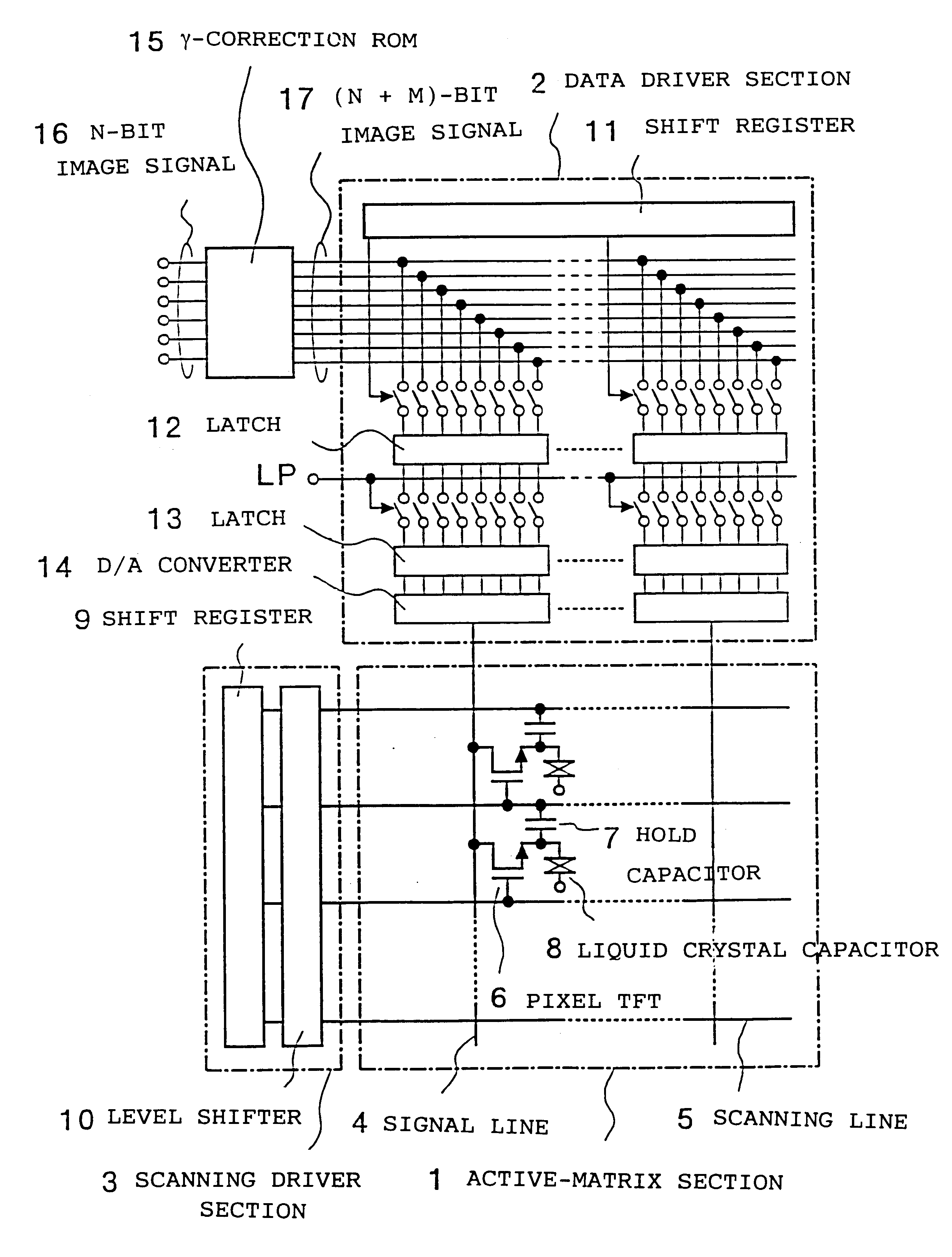
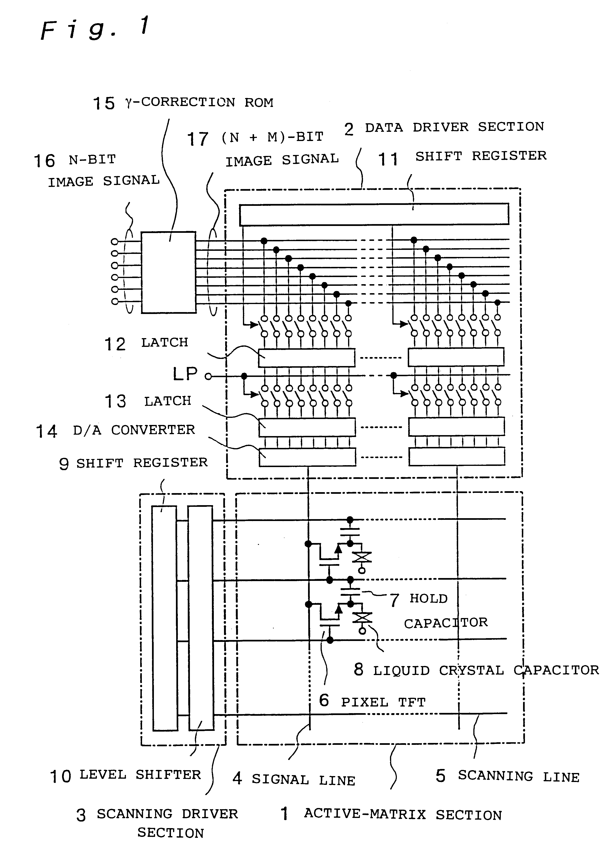
A liquid crystal display apparatus according to the present embodiment will be described below by referring to the drawings. FIG. 1 is a circuit diagram of a liquid crystal display apparatus. The liquid crystal display apparatus having thin-film transistors (TFTs) will be described. In an active matrix section 1 for conducting image display, signal lines 4 and scanning lines 5 are disposed in a matrix manner, and at an intersection thereof a pixel TFT 6, a hold capacitor 7, and a liquid crystal capacitor 8 are connected. A scanning driver section 3 for supplying a selection pulse to scanning lines 4 is formed by a shift register 9 and a level shifter 10. The level shifter 10 is provided with a buffer circuit at its output section in many cases. A data driver section 2 for sending an image signal to signal lines 4 is formed by a shift register 11, latches 12 for reading data from a (n+m)-bit digital image signal 17 according to the output timing of the shift register 11...

embodiment 2

(Embodiment 2)

In the present embodiment, a driving method for a liquid crystal display apparatus will be described. In FIG. 1, the n-bit image signal 16 is converted to the (n+m)-bit image signal 17 by the sequential-g-correction ROM 15 and is input to the data driver section 2. How to create a g-correction table to be stored in the g-correction ROM will be described below. The transmission ratio of the liquid crystal display apparatus is measured, and a chart indicating the dependency of the transmission ratio on the input voltage is made with the transmission ratio being assigned to the vertical axis and the input voltage being assigned to the horizontal axis. Then, on the horizontal axis indicating the input voltage, 2n+m voltages which can be output from the (n+m)-bit D / A converter are plotted. The transmission ratios which are to be obtained for n-bit gray-scale display are plotted on the vertical axis, horizontal parallel lines are drawn from those points to the transmission-f...

embodiment 3

(Embodiment 3)

A liquid crystal display apparatus which can provide high image quality by reducing noise will be described below in the present embodiment. In general, a digital driver having a multiple-bit D / A converter is likely to receive various types of noise during conversion.

FIG. 9 shows a circuit diagram of a typical shift register circuit used for a digital driver and a timing chart thereof. In this circuit, by the use of clock signals having phases shifted by 180 degrees, a selection pulse can be shifted by a half of the period of the clock signals. This circuit transfers a pulse in either directions. A pulse is transferred in the right direction with R set to high and L set to low, and is transferred in the left direction with R set to low and L set to high. The timing of the rising edges and the falling edges of the clock signals for the shift register is the same as that of switching in each dot in a digital image signal. To minimize the effects of these clock signals an...


PUM

PropertyMeasurementUnit
power source voltageaaaaaaaaaa
voltagesaaaaaaaaaa
voltageaaaaaaaaaa

Abstract

An n-bit digital image data is converted to (n+m)-bit data with a g-correction table, and displayed by the use of a (n+m)-bit D/A converter. A peripheral-driver logic section is driven with a low-voltage common power source and countermeasures to noise are taken. Data input to the D/A converter is not reversed and the power to the D/A converter is made alternating to apply an AC voltage to aligned crystal layer. A circuit is provided in order to compensate for a delay time in the driver. With this configuration, the image quality of a liquid crystal display apparatus in which the D/A converter is built is improved.

Description

BACKGROUND OF THE INVENTION1. Field of the InventionThe present invention relates to a liquid crystal display apparatus, a driving method therefor, and a display system.2. Background of the InventionA conventional liquid crystal display apparatus is, for example, disclosed in the Japanese Unexamined Patent Publication No. 6-222741. FIG. 2 is a circuit diagram of a data driver in the liquid crystal display apparatus. Data driver systems for writing an image signal into a liquid crystal display apparatus generally includes an analog system and a digital system. Since the analog system consumes a large power in the circuit, it is not suited to a display for a portable computer. In contrast, the digital system consumes a small power, but it requires that an output voltage be supplied from the outside and the number of external power sources becomes large. There is a system in which a D / A converter is built and the number of external power sources is made minimum. Since the output voltag...

Claims


Application Information

Patent Timeline
Patent Type & Authority Patents(United States)
IPC IPC(8): G09G3/36G02F1/136G02F1/133G02F1/1368G09G3/20
CPCG09G3/2011G09G3/3611G09G3/3688G09G3/3614G09G2320/0276G09G2310/027G09G2310/0283
Inventor MATSUEDA, YOJIRO
Owner BOE TECH GRP CO LTD
Why Eureka
Try Eureka