Method for driving electrooptical device, driving circuit, and electrooptical device, and electronic apparatus

Inactive Publication Date: 2005-03-29
SEIKO EPSON CORP
View PDF16 Cites 10 Cited by
  • Summary
  • Abstract
  • Description
  • Claims
  • Application Information

AI Technical Summary

Benefits of technology

According to the first embodiment, in one field, the period during which a pixel is turned on (or off) is pulse-width modulated according to the tone of that pixel, resulting in a tone display using an effective voltage control. In this case, in each of the sub-fields, a binary signal (that is, a digital signal which can only take either of a H-level or L-level) which indicates that the pixel is turned on or off is used to select any one of a first voltage, a second voltage, and a voltage equal to the reference voltage. This suppresses nonuniform display caused by nonuniformity in component characteristics, wiring resistance, etc., and as a result, a high-quality and high-definition tone display is achieved.
Furthermore, the voltage level at which the first scanning signal allows the switching element connected to the first scanning line to be turned on and the voltage level of the first voltage is the same, and the voltage level at which the second scanning signal allows the switching element connected to the second scanning line to be turned on and the voltage level of the second voltage is the same, thereby advantageously, reducing the number of levels of the voltages used in the driving circuit of the electro-optical device, and thus providing simplification of the structure of circuit to generate the voltages.

Problems solved by technology

This requires a D / A converting circuit, an operational amplifier, etc. as peripheral circuits of the electro-optical device, leading to increased cost of the overall device.
Furthermore, since a nonuniform display can be caused by nonuniformity in characteristics of the D / A converting circuit, the operational amplifier, etc., various wiring resistances, etc., there is a problem in that it is extremely difficult to achieve a high-quality display.
This problem is noticeable in particular when a high-definition display is desired.

Method used


Image

  • Method for driving electrooptical device, driving circuit, and electrooptical device, and electronic apparatus
  • Method for driving electrooptical device, driving circuit, and electrooptical device, and electronic apparatus
  • Method for driving electrooptical device, driving circuit, and electrooptical device, and electronic apparatus

Examples


first embodiment

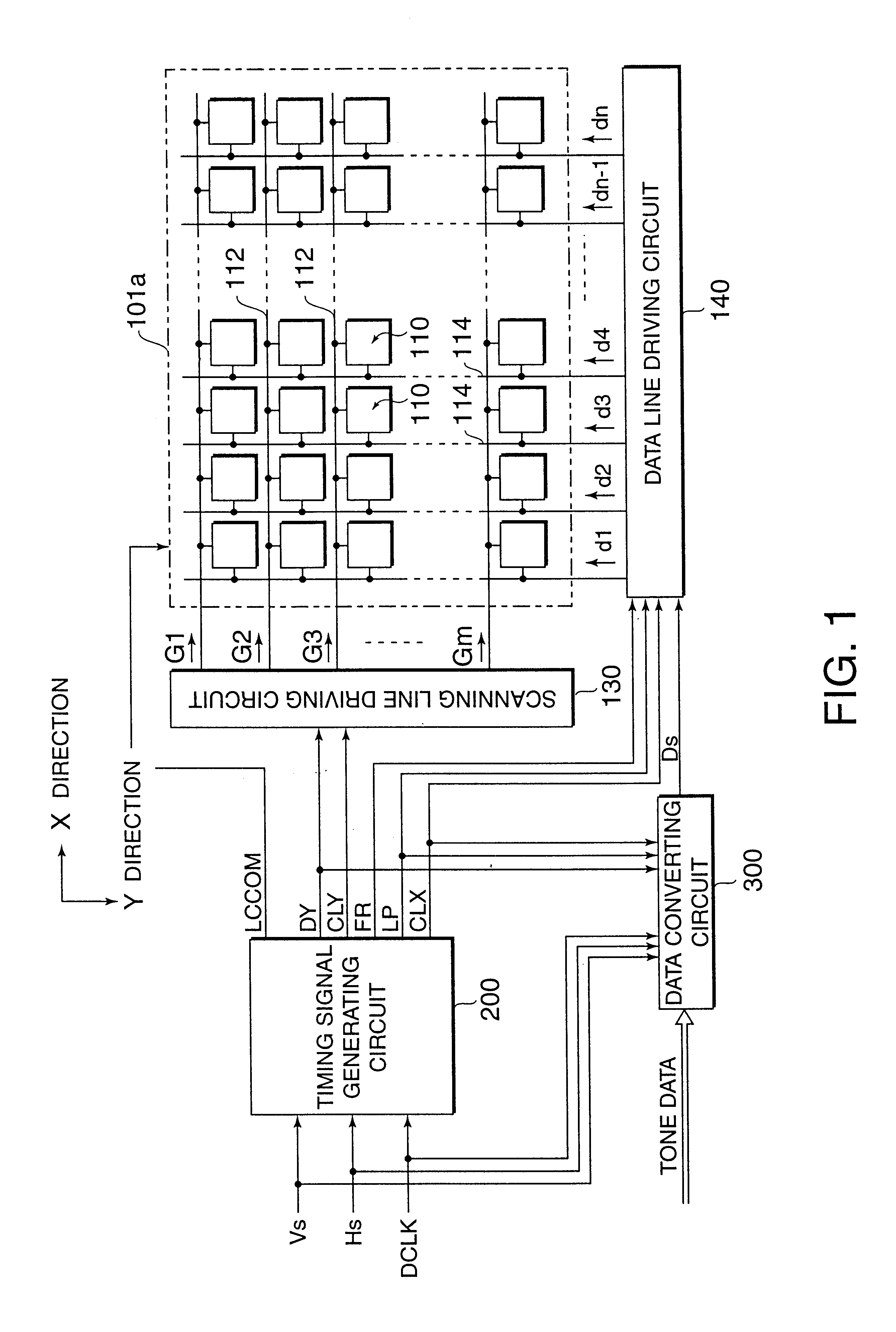
FIG. 1 is a block diagram of the electrical structure of an electro-optical device according to the present invention. The electro-optical device is implemented by a liquid crystal display which uses a twisted nematic (TN) liquid crystal as an electro-optical material, including an element substrate and an opposing substrate which are bonded at a constant spacing therebetween such that the liquid crystal as an electro-optical material is interposed in the spacing. In the electro-optical device, the element substrate is implemented by a transparent substrate made of glass, quartz, or the like, and thin film transistors (TFTs) for driving pixels, complementary TFTs which form a peripheral driving circuit, etc., are formed on the element substrate.

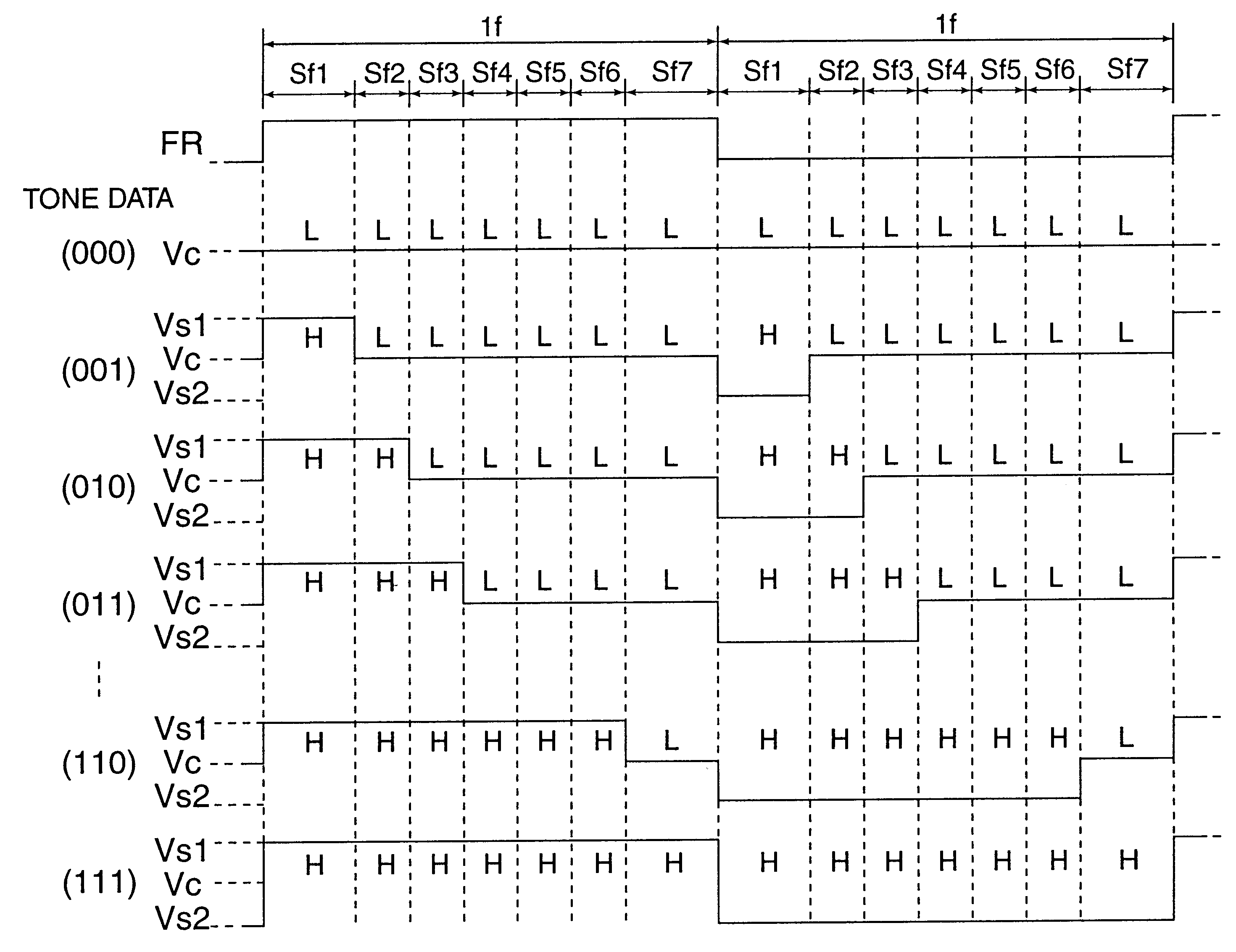
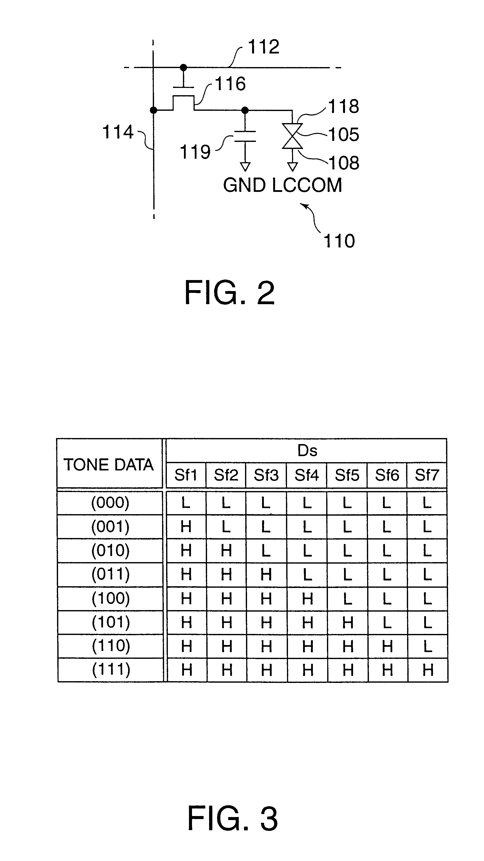
As shown in FIG. 1, a display region 101a on the element substrate can includes a plurality of scanning lines 112 extending in the X (row) direction, and a plurality of data lines 114 extending in the Y (column) direction. Pixels 110 are arra...


PUM


Abstract

The invention provides an electro-optical device capable of a high-quality and high-definition tone display, a driving method thereof, a driving circuit thereof, and electronic equipment using the same. With the invention, one field is divided into a plurality of sub-fields, such that each pixel is turned on or off in each of the sub-fields so that the proportion of the period during which each pixel is turned on to the period during which the associated pixel is turned off within the one field corresponds to the proportion according to the tone data. Further, when each pixel is turned on, either a first voltage which is higher than a constant reference voltage applied to a counter electrode or a second voltage which is lower than the reference voltage is applied to a pixel electrode of the associated pixel, and when the pixel is turned off, a voltage equal to the reference voltage is applied to the pixel electrode of the pixel.

Description

BACKGROUND OF THE INVENTION1. Field of InventionThe present invention relates to a driving method and a driving circuit of an electro-optical device that performs a tone display control by modulation on the time axis and an electro-optical device and electronic equipment.2. Description of Related ArtElectro-optical devices, such as liquid crystal display devices using liquid crystal as an electro-optical material, are widely used in display units of various information processors, liquid crystal television sets and the like as display devices. Such devices are taking the place of cathode-ray tubes (CRTs).For example, a conventional electro-optical device includes pixel electrodes which are arranged into a matrix, an element substrate having switching elements such as TFTs (thin film transistors) coupled to the pixel electrodes, an opposing substrate on which counter electrodes which oppose the pixel electrodes are formed, and a liquid crystal serving as an electro-optical material w...

Claims


Application Information

Patent Timeline
IPC IPC(8): G09G3/36G09G3/20
CPCG09G3/3648G09G3/2025G09G2300/0823G09G2300/0814G09G3/3696G02F1/133
Inventor INOUE, AKIRAITO, AKIHIKOISHII, RYOYAMAZAKI, SUGURU
Owner SEIKO EPSON CORP
Why Eureka
Try Eureka