Optical resonance analysis system

a technology of optical resonance and analysis system, applied in the field of optical resonance analysis system, can solve the problems of increasing the spr linewidth and grating performance anomalies, and achieve the effect of low cos

Inactive Publication Date: 2005-03-29
APPL BIOSYSTEMS INC
View PDF24 Cites 38 Cited by
  • Summary
  • Abstract
  • Description
  • Claims
  • Application Information

AI Technical Summary

Benefits of technology

The invention is further directed toward utilizing a diffraction grating or a diffractive optical element as a pre-dispersive or post-dispersive element in the analysis system allowing the use of low cost, broad band light sources.
The invention is further directed toward an anamorphic optical design that allows the analysis system to generate and detect resonances, from a one dimensional array of sites on the same substrate, simultaneously.

Problems solved by technology

However, to obtain the information to determine the genetically relevant data, thousands of tests need to be run on one sample if conventional technologies are used.
As gratings play an important role in promoting the surface plasmon, this in turn means that the surface plasmon causes some anomalies to grating performance.
Addition of radiative coupling or other losses can only increase the SPR linewidth.

Method used


Image

  • Optical resonance analysis system
  • Optical resonance analysis system
  • Optical resonance analysis system

Examples


embodiment

Utilizing Wavelength Scanning

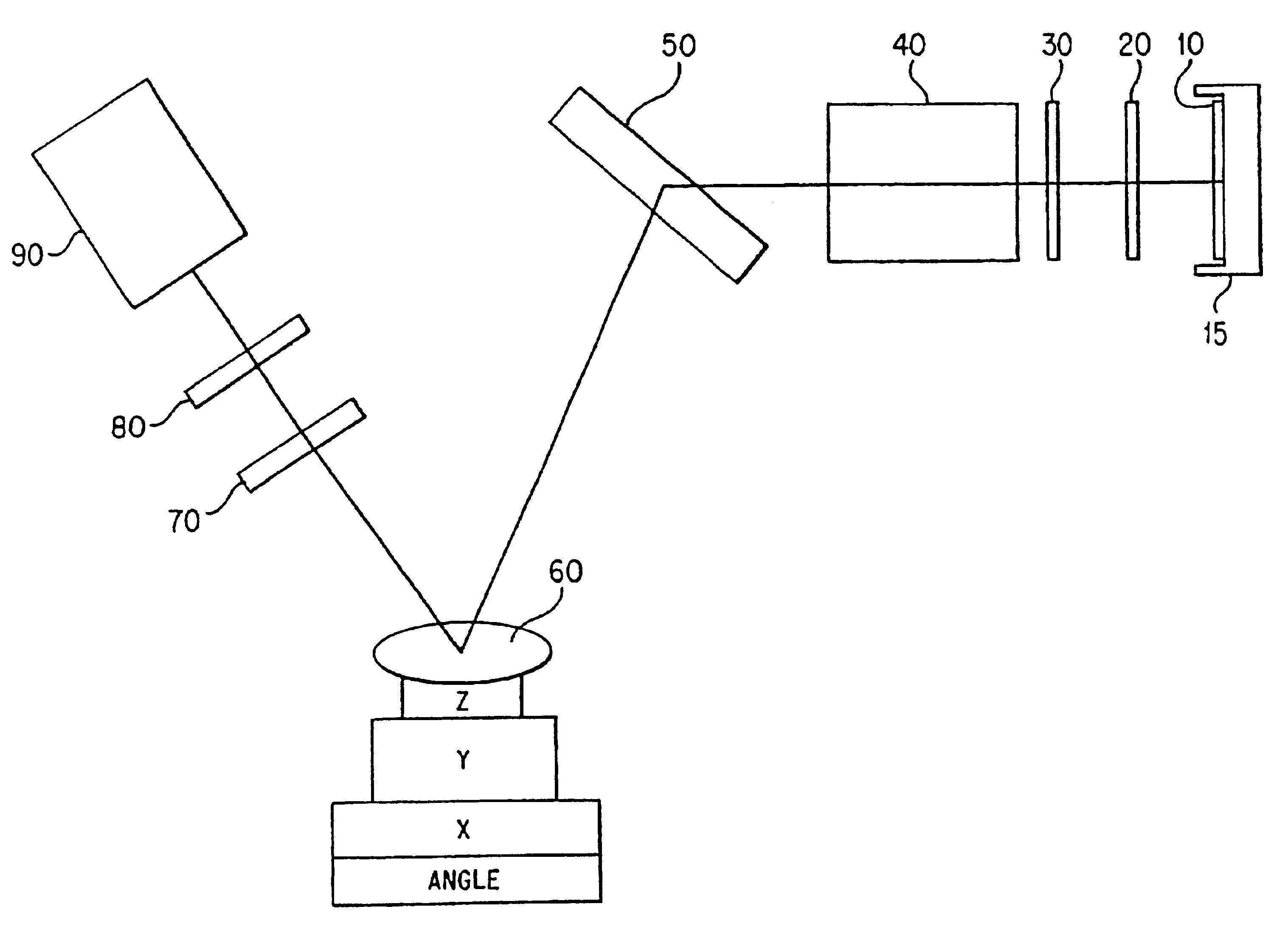
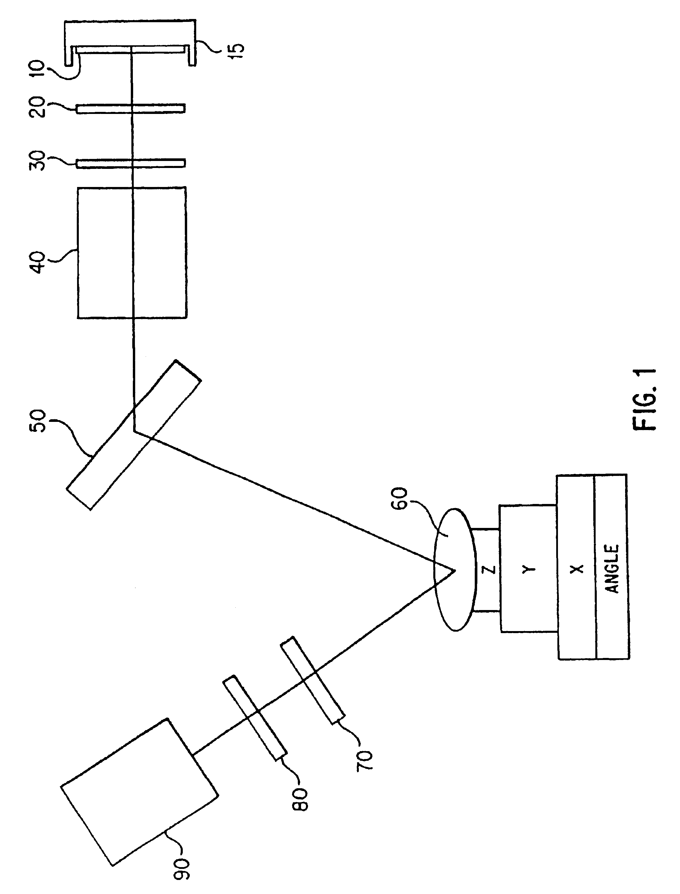
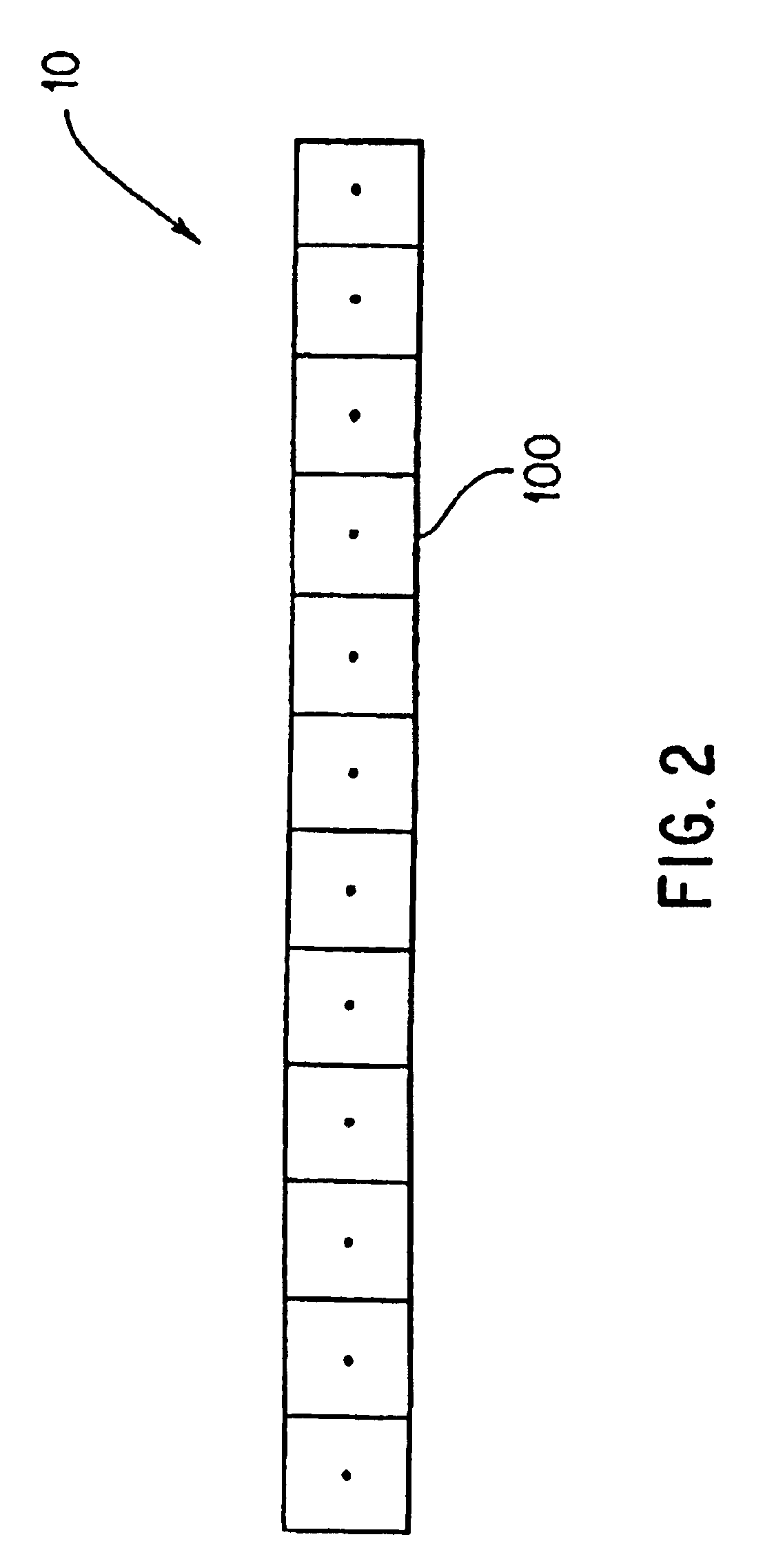
FIG. 9 shows an embodiment of the invention directed toward wavelength scanning. Light emitted from the source 10 travels through an optical system 130 and impinges on a sensor 60. Light reflected from the sensor 60 then travels the detector 90. The wavelength scanning means may comprise the optical system 130 which may be a spectrometer, a grating, an acousto-optical tunable filter, a Fabrey-Perot or Fourier transform interferometer, a liquid crystal filter, a tilting dielectric filter, a linear variable filter, a Lyot filter, or a tunable laser. Alternatively the wavelength scanning means may comprise the source 10 and the optical system 130, where the source is a linear array as shown in FIG. 2 or a two dimensional array as shown in FIG. 3 and the individual elements of the array produce different wavelengths. In this particular embodiment the optical system 130 serves to focus the different wavelengths onto appropriate areas of the sensor.


PUM

PropertyMeasurementUnit
optical resonance analysisaaaaaaaaaa
wavelengthsaaaaaaaaaa
fixed wavelengthaaaaaaaaaa

Abstract

An optical resonance analysis system comprising a sensor means (60) and an illumination means (400) for generating non-monochromatic illumination. The illumination means (400) further comprises a means for generating illumination at a plurality of angles, a lens system for projecting said illumination at said plurality of angles (390) and a dispersive device (380) for dispersing said illumination at each of said plurality of angles so that there is a correlation between said plurality of angles and the wavelengths of said illumination such that a resonance condition is generated on said sensor mean (60) for all wavelengths generated by said non-monochromatic source simultaneously. The analysis system also comprises a detection means (90) for detecting the reflected or transmitted illumination. Another embodiment comprises an anamorphic imaging means (120).

Description

FIELD OF THE INVENTIONThis invention relates generally to optical resonance analysis systems, specifically to certain sensor design aspects and to analysis systems comprising illumination and detection systems that utilize those sensors for analysisBACKGROUND OF THE INVENTIONBecause of the recent surge in applications, sensor based instruments are becoming very popular. This growth in applications has been primarily spurred by the biotechnology and the pharmaceutical industries especially from the enormous influx of information from the Human Genome Program. This drove of information has resulted in a corresponding spawning of new industries. Some of the newest, rapidly growing industries are: proteomics, where proteins, function and genomics come together; and pharmacokinetics where researchers attempt to find products of combinatorial synthesis that have binding properties to unique sites such as receptors, that typically result in a biological altering event. Both technologies re...

Claims


Application Information

Patent Timeline
Patent Type & Authority Patents(United States)
IPC IPC(8): G01N21/55G01N21/27
CPCG01N21/7703G01N21/553
Inventor BAHATT, DARCAHILL, JERRY E.NISHIKIDA, KOICHIPICOZZA, ENRICO G.SAVIANO, PAUL G.TRACY, DAVID H.WANG, YONGDONG
Owner APPL BIOSYSTEMS INC
Why Eureka
Try Eureka