
Write head with high moment film layer having tapered portion extending beyond write gap layer

a write head and film layer technology, applied in the field of magnetic recording heads, can solve problems such as the loss of magnetic field strength, and achieve the effect of preventing oxidation or corrosion of high moment materials

Inactive Publication Date: 2005-03-29
WESTERN DIGITAL TECH INC
View PDF16 Cites 148 Cited by
  • Summary
  • Abstract
  • Description
  • Claims
  • Application Information

AI Technical Summary

Benefits of technology

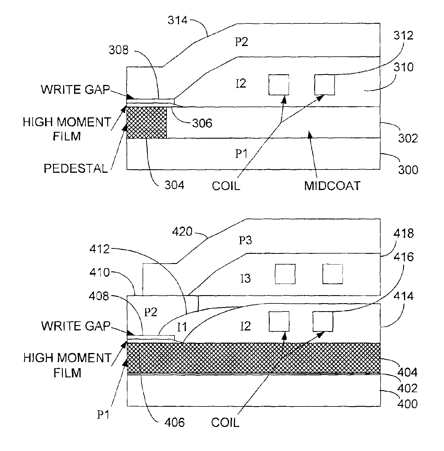
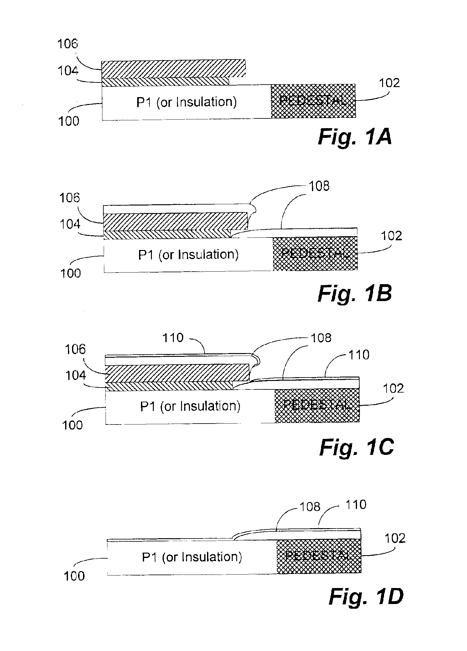
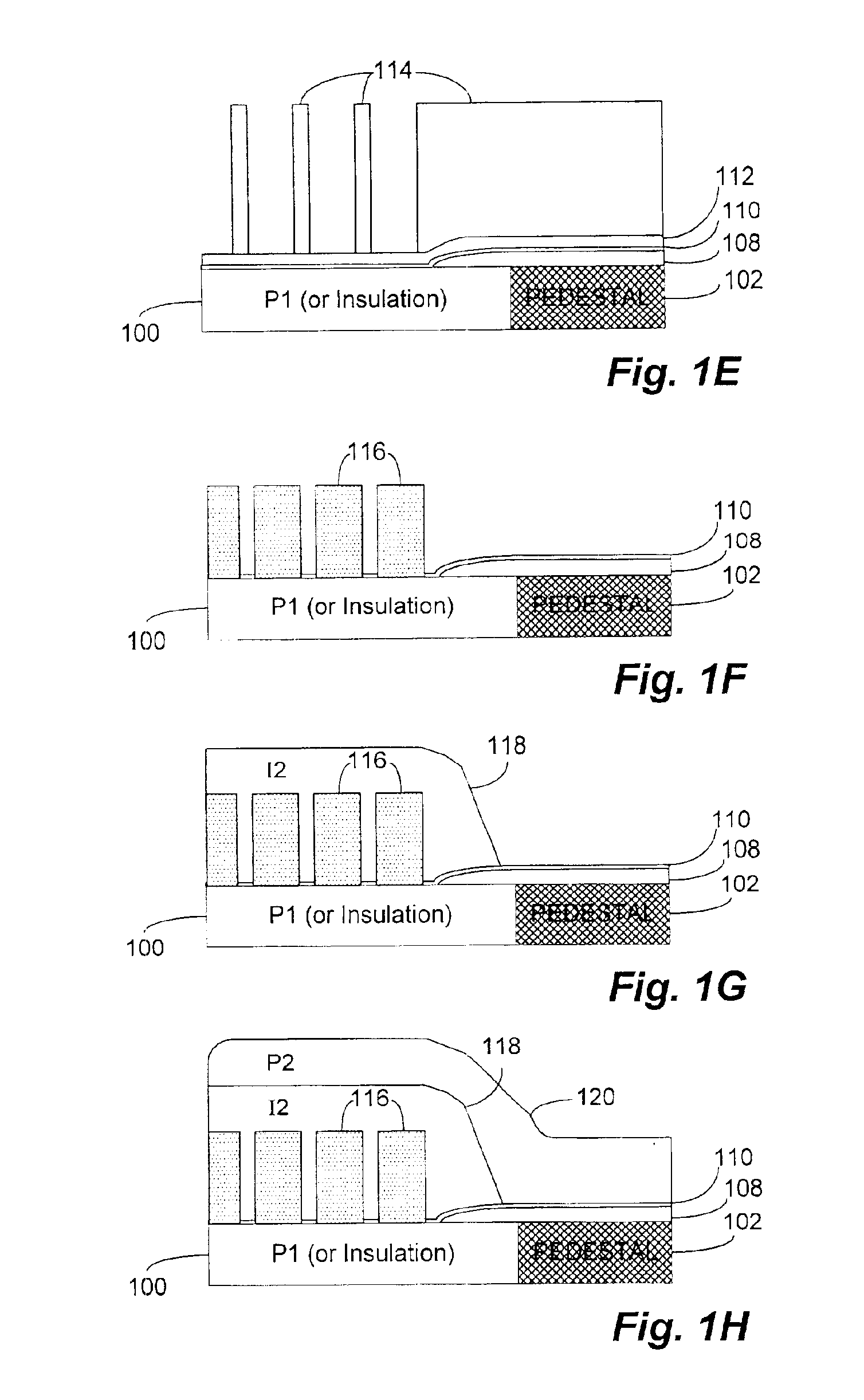
In accordance with a representative process disclosed herein, a lift-off photoresist mask is used prior to the deposition of the high moment sputtered film. Following the lift-off process, the high moment film remains on the P1 pedestal (in the case of a PDZT type write head) or on the P1 itself (in the case of a Stitched Pole write head). The edge of the lift-off sputtered film is then covered by cured photoresist insulation which is placed at a distance away from the air bearing surface (“ABS”). The coverage of insulation at the edge of the sputtered film is desirable in order to avoid forming a topographic step which may have undesired consequences in the subsequent top pole formation processes. In the case of PDZT type write heads, the lift-off sputtered film extends further away from the ABS than the zero-throat defining pedestal while in the case of a Stitched Pole write head, the photoresist insulation is at a short distance (throat height) away from the ABS. A gap layer is used to cover the sputtered film after the lift-off process. This prevents oxidation or corrosion of the high moment materials during the high temperature cure of the photoresist insulation.

Problems solved by technology

Moving significantly in any direction away from a “one” causes a dramatic loss of magnetic field strength.
However, neither of these patents address the coverage of the edge of the flux enhanced layer by an insulating layer to avoid forming a topographic step which may have undesired consequences in the subsequent top pole formation processes.

Method used


Image

  • Write head with high moment film layer having tapered portion extending beyond write gap layer
  • Write head with high moment film layer having tapered portion extending beyond write gap layer
  • Write head with high moment film layer having tapered portion extending beyond write gap layer

Examples


Embodiment Construction

With reference now to FIG. 1A, a simplified cross-sectional view of one of a sequence of steps which may be utilized in order to produce a PDZT write head in accordance with a representative implementation of the present invention is shown. As illustrated, a bottom pole (“P1”) or insulation layer (e.g. Al2O3 and the like) 100 is provided in conjunction with a pedestal structure 102.

The pedestal structure 102 may comprise conventional electroplated CoNiFe or other NiFe alloys and is planarized with the bottom pole 100 (for example, using chemical mechanical polishing (“CMP”) techniques) to provide a combined structure having a thickness of approximately 1.0 μm. Overlying the bottom pole 100 and pedestal 102 is a patterned polymethylglutarimide (“PMGI”) layer 104 and photoresist layer 106. The PMGI layer 104 dissolves relatively more quickly than the photoresist layer 106 in the developer agent. The photoresist layer 106 forms an overhang with respect to the PMGI layer 104 as shown wh...


PUM


Abstract

An inductive write head structure incorporating a high moment film in conjunction with at least one pole (e.g., the bottom pole) for use with magnetic storage media and a process for producing the same in which a lift-off photoresist mask is used prior to the deposition of the high moment sputtered film. Following the lift-off process, the high moment film remains on the bottom pole (“P1”) pedestal (in the case of a PDZT type write head) or on the P1 itself (in the case of a Stitched Pole write head). The edge of the lift-off sputtered film is then covered by cured photoresist insulation which is placed at a distance away from the air bearing surface (“ABS”). The coverage of insulation at the edge of the sputtered film is desirable in order to avoid forming a topographic step which may have undesired consequences in the subsequent top pole formation processes.

Description

BACKGROUND OF THE INVENTIONThe present invention relates, in general, to the field of magnetic recording heads. More particularly, the present invention relates to an inductive write head structure incorporating a high moment film in conjunction with at least one pole (e.g., the bottom pole) for use with magnetic storage media and a process for producing the same.Recording heads are miniature components (with dimensions of on the order of about 1 mm2) that read and write information to and from a hard-drive disk or another storage medium. When writing, the head acts as a small electromagnet wherein positive and negative pulses of current are translated into north and south magnetic poles on a rotating magnetic disk. When reading, the head senses magnetic fields from these poles and translates the alternating fields into positive and negative voltage pulses. These pulses become the bits of digital information stored on the disk. A recording head is generally bonded or otherwise affix...

Claims


Application Information

Patent Timeline
IPC IPC(8): G11B5/31G11B5/40G11B5/39
CPCB82Y10/00B82Y25/00G11B5/313G11B5/3153G11B5/3133G11B5/3106G11B2005/3996G11B5/3163G11B5/40
Inventor CHEN, YINGJIANDANG, XIAOZHONG
Owner WESTERN DIGITAL TECH INC
Learn More