Integrated solenoid system

a solenoid and integrated technology, applied in the direction of motor/generator/converter stopper, dynamo-electric converter control, instruments, etc., can solve the problems of increasing affecting the performance of the solenoid, and requiring far more force than required, so as to improve the cost effectiveness of a typical solenoid application, and increase the overall size of the solenoid

Inactive Publication Date: 2005-03-29
TRUMPET HLDG
View PDF7 Cites 17 Cited by
  • Summary
  • Abstract
  • Description
  • Claims
  • Application Information

AI Technical Summary

Benefits of technology

The present invention provides solenoid operational control by encasing the electronic control in the solenoid housing. By minimizing the control size, the invention provides more operational capacity without increasing the overall size of

Problems solved by technology

As a result, without any compensating means, the performance of a solenoid is affected by variations in applied voltage and by variations in coil temperature.
These can be particularly demanding because operating voltage levels can vary greatly.
Accordingly, it will have far more force than required and consume far more power than required when conditions are at maximum or even nominal values.
T

Method used


Image

  • Integrated solenoid system
  • Integrated solenoid system
  • Integrated solenoid system

Examples


Embodiment Construction

The present invention is depicted in FIGS. 1 through 7. Like parts illustrated and described herein are designated by like reference numerals.

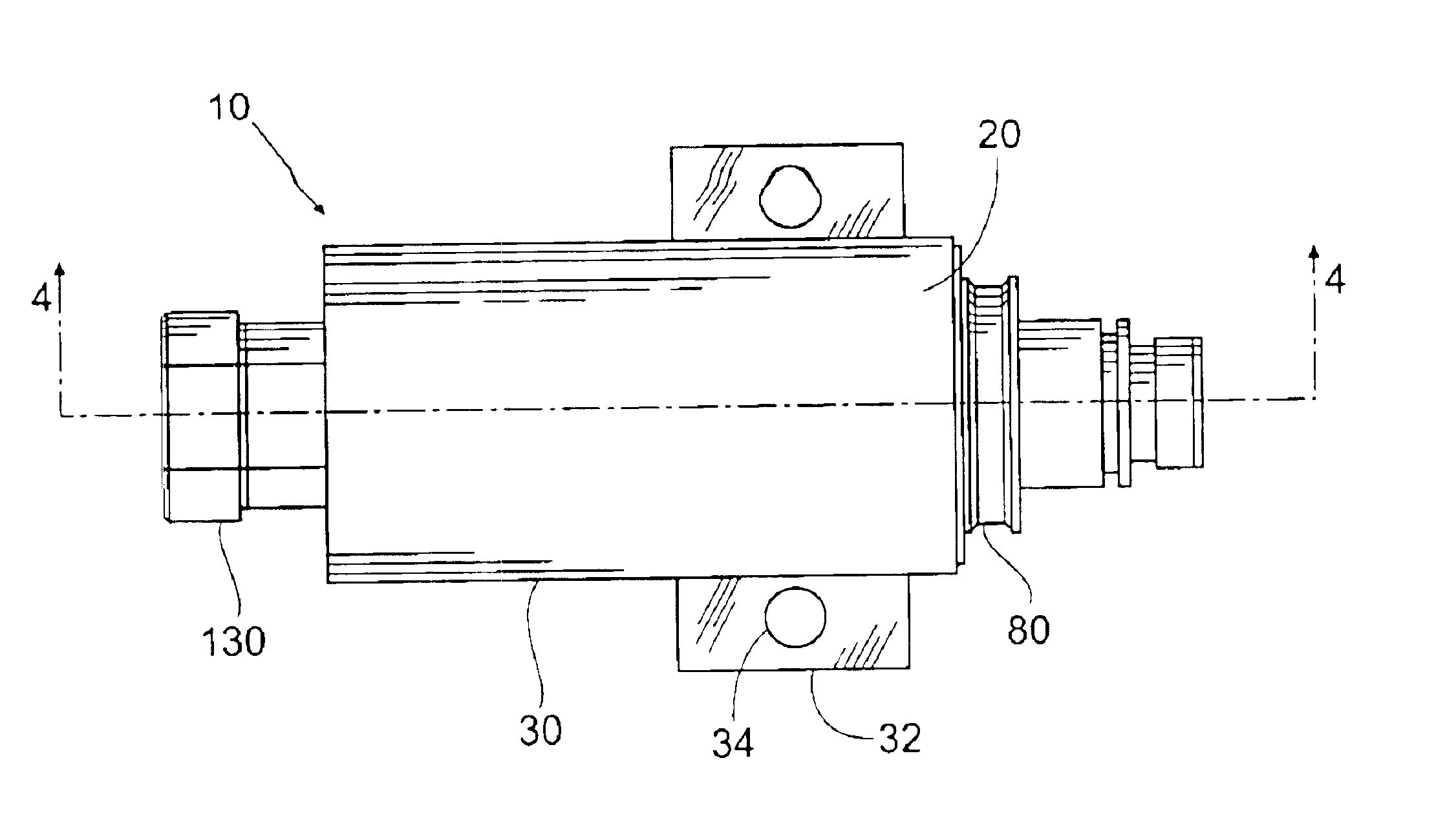
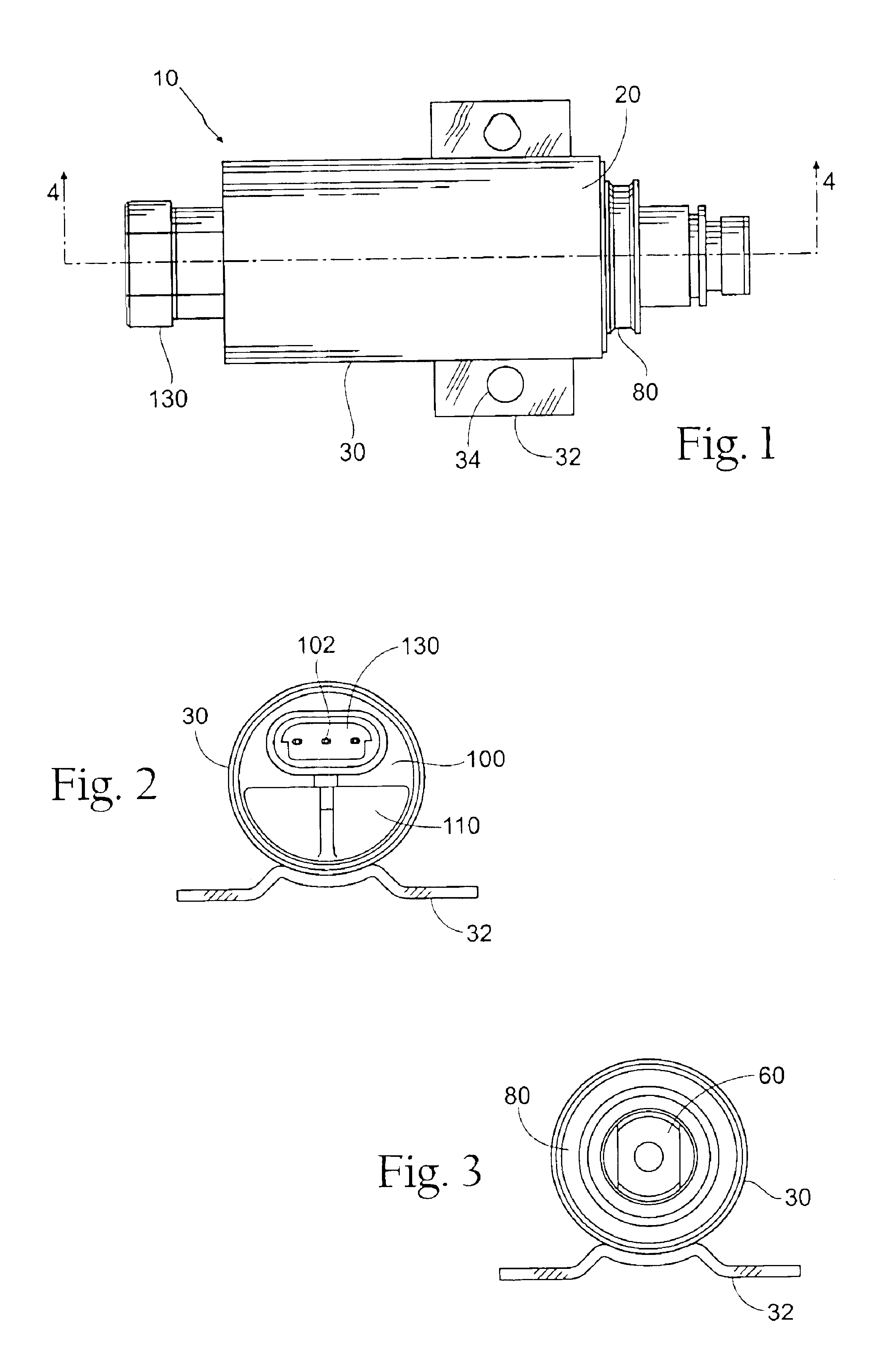
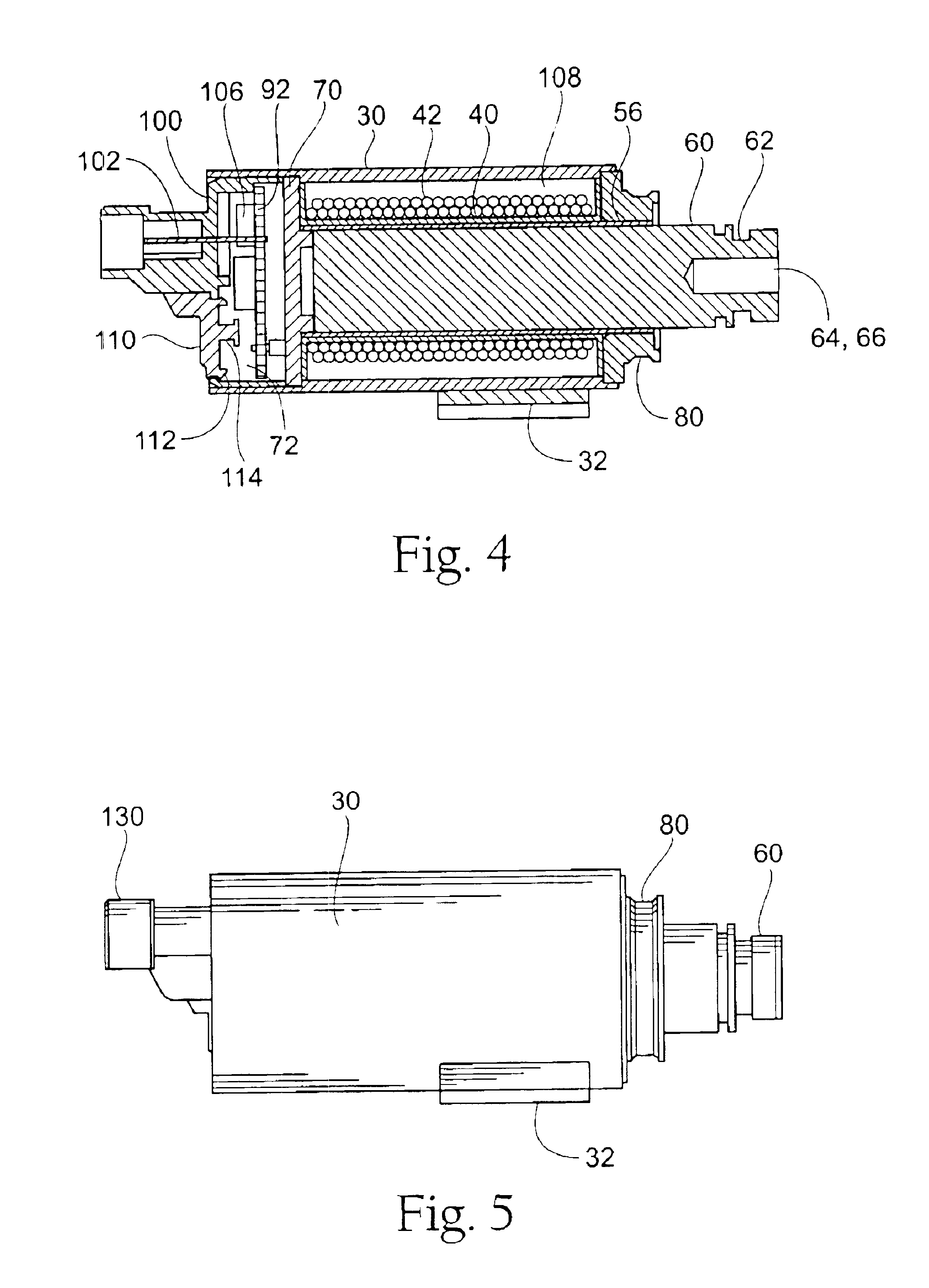
Referring to the drawings, and partiuculary to FIGS. 1 and 6 there is illustrated a solenoid 20. The solenoid 20 is enclosed within a housing 30. The housing may be formed from steel tubing or any other suitable material. In one embodiment and for purposes of example only, the housing is approximately 3.08 inches in length and has a diameter of 1.625 inches. A saddle type side mounting bracket 32 with two (2) holes 34 on 2.00 inch centers is attached to the housing 30 for mounting or mechanical interface.

Within the housing 30 is placed the bobbin 40 that is wound with magnetic wire 42. The bobbin 40 is preferably fabricated from a nylon material and includes two passageways 44, 46 on one end. The first passageway 44 is formed where the tube portion 48 of the bobbin meets the side 50 and allows one end of the winding wire 42 to pass there throu...


PUM


Abstract

An integrated solenoid system including a single housing containing a solenoid, a controller and one or more electrical connections. The controller includes temperature compensating means and/or voltage compensating means thereby providing predetermined, substantially constant currents to said solenoid. The housing includes an integral two-part end cover.

Description

FIELD OF THE INVENTIONThis invention relates generally to an integrated system solenoid, and in particular to a single housing containing a solenoid, controller and one or more electrical connections.BACKGROUND OF THE INVENTIONA solenoid is a common electrical device used to convert electrical energy into mechanical energy. Solenoids are well known in the art and are often utilized as a means of moving a component a predetermined distance at a predetermined time. In its most basic form, a solenoid is an electro-mechanical device that converts electrical energy into linear or rotary motion. Electrical current passes through a coil of insulated copper wire producing a magnetic field, which moves a ferro-magnetic plunger located within the core of the coil. Steel parts surround the coil to contain the flux path for maximum pull, push or rotational force. A solenoid can be used to open a valve, activate a switch, apply a brake or a number of other activities where mechanical movement is...

Claims


Application Information

Patent Timeline
IPC IPC(8): F16K31/06H01H47/22H01H47/26H01H50/16
CPCF16K31/0675H01H47/26H01H50/16
Inventor MALLER, DENNIS A.MCMAHON, TODD
Owner TRUMPET HLDG
Why Eureka
Try Eureka