Check patentability & draft patents in minutes with Patsnap Eureka AI!

Structure of fuel injector using piezoelectric actuator

a piezoelectric actuator and fuel injector technology, applied in the direction of fuel injection apparatus, spraying apparatus, charge feed system, etc., can solve the problems of insulator tube breakage, inconvenient replacement of parts, and inability to finely adjust the characteristics of fuel injection,

Inactive Publication Date: 2005-04-05
DENSO CORP
View PDF30 Cites 28 Cited by
  • Summary
  • Abstract
  • Description
  • Claims
  • Application Information

AI Technical Summary

Benefits of technology

[0012]Other objects of the invention are to provide an improved structure of a fuel injector which is easy to install, to remove a piezoelectric actuator in and from the fuel injectors and to adjust fuel injection characteristics finely which allows an overall size of the fuel injector to be decreased.
[0020]The fastening member is fastened to the opening of the vertical chamber in the housing to hold the actuator detachably within the vertical chamber. A positioning means is provided for positioning the actuator within the vertical chamber without being subjected to torque or unbalanced load arising from fastening of the fastening member.
[0024]At least one fragile portion may be formed on the housing for facilitating ease of cutting or breaking up the housing for withdrawing the actuator.

Problems solved by technology

It is, thus, quite inconvenient.
Further, there is a problem that parts cannot be removed from the housing after assembly thereof, therefore, it is impossible to replace the parts and adjust characteristics of the fuel injection finely.
The piezoelectric device, the insulator tube, and the connector are not secured completely during assembly thereof and thus are not easy to handle, which may lead to the breakage of the insulator tube.
Accordingly, it is necessary to prepare a connector mold for every type of engine, resulting in an increase in manufacturing cost of the injector.
This structure, however, has the drawbacks in that the bellows has a larger diameter and is difficult to install in small-sized fuel injectors.
If the size of the piezoelectric device is decreased to match with that of the fuel injectors, it may cause the performance thereof to be reduced.
For theses reasons, fuel injectors equipped with the piezoelectric device as an actuator are not yet put into practical use.

Method used


Image

  • Structure of fuel injector using piezoelectric actuator
  • Structure of fuel injector using piezoelectric actuator
  • Structure of fuel injector using piezoelectric actuator

Examples


seventh embodiment

tional view which shows an actuator according to the invention;

[0059]FIG. 15 is a vertical sectional view which shows an actuator according to the eighth embodiment of the invention;

[0060]FIG. 16 is a vertical sectional view which shows an actuator according to the ninth embodiment of the invention;

[0061]FIG. 17 is a vertical sectional view which shows an actuator according to the tenth embodiment of the invention, FIGS. 18(a), 18(b), 18(c), and 18(d) are sectional views which show modifications of the actuator of FIG. 17;

[0062]FIGS. 19(a), 19(b), 19(c), 19(d), 19(e), and 19(f) are sectional views which show modifications of the actuator of FIG. 10;

[0063]FIGS. 20(a), 20(b), 20(c), 20(d), 20(e), and 20(f) are sectional views which show modifications of the actuator of FIG. 15;

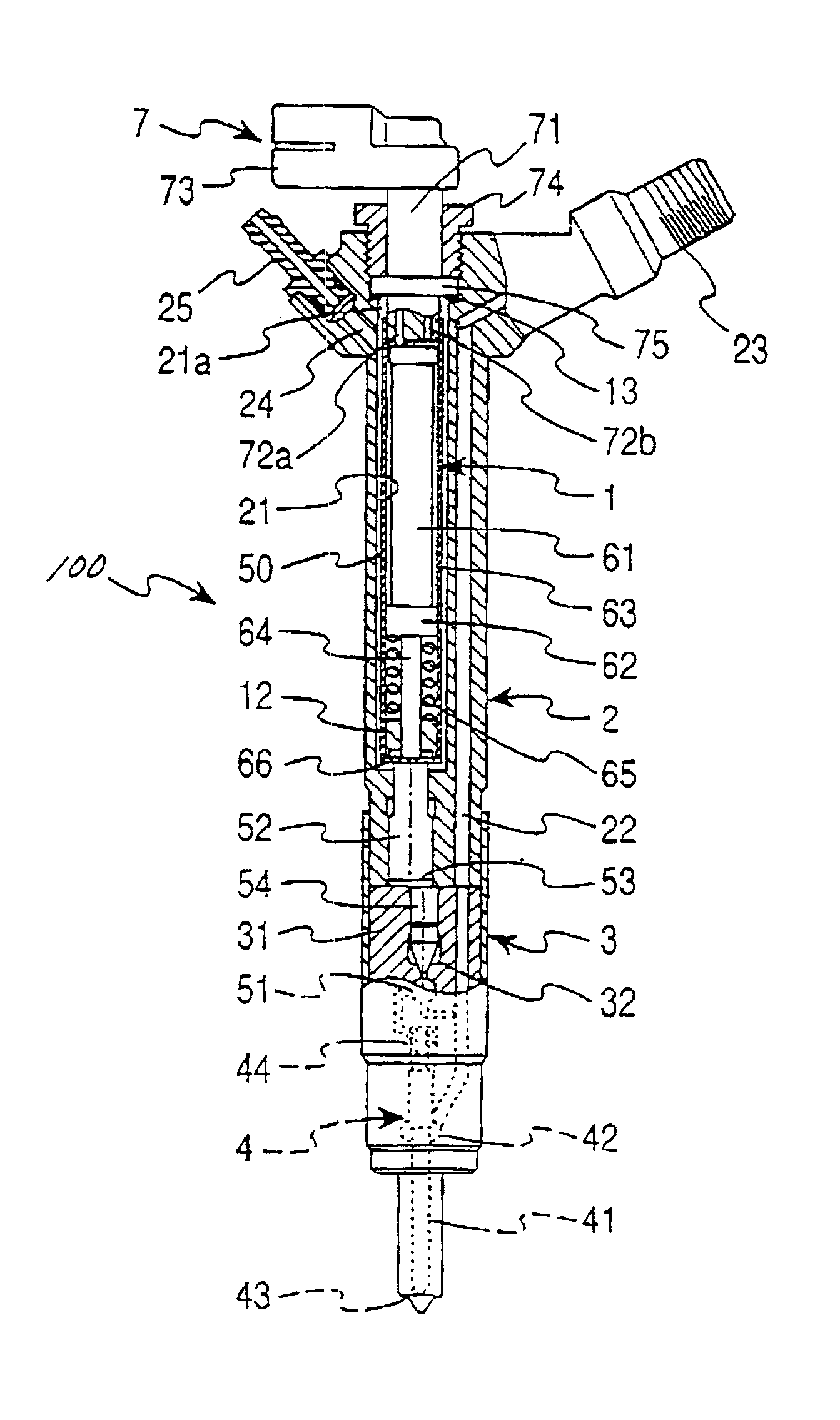
[0064]FIG. 21 is a partially sectional view which shows a fuel injector according to the eleventh embodiment of the invention;

[0065]FIG. 22 is a partially sectional view which shows a fuel injector according to ...


PUM


Abstract

A fuel injector for an internal combustion engine is provided. The fuel injector has a simple structure so that it is easy to install and remove a piezoelectric valve actuator in and from the fuel injector, and to adjust fuel injection characteristics finely which allows the overall size of the fuel injector to be decreased. The fuel injector includes a housing to be installed in the engine and a structural element serving to install the piezoelectric valve actuator in the housing to be detachable easily. The piezoelectric valve actuator is retained in an actuator casing fitted in the housing so that it can expand or contract to move a needle valve. The actuator casing has an extensible portion in itself or is coupled to a bellows in alignment for enabling the piezoelectric valve actuator to expand, thereby allowing the size of the actuator casing to be minimized.

Description

BACKGROUND OF THE INVENTION[0002]1. Technical Field of the Invention[0003]The present invention relates generally to a fuel injector for internal combustion engines, and more particularly to an improved structure of a fuel injector for installation of a piezoelectric device used as a valve actuator of the fuel injector.[0004]2. Background Art[0005]Typical fuel injectors used in, for example, internal combustion diesel engines of automotive vehicles are designed to drive a three-way valve or a two-way valve connected to a common rail in which a high pressure fuel is stored for opening and closing a fuel supply passage selectively. When it is required to inject the fuel into the engine, the fuel injector changes the fuel pressure acting on a needle to lift up the needle for opening a spray hole to initiate the fuel injection.[0006]As a valve actuator to open and close the three-way valve or the two-way valve, a solenoid valve has been usually used. In recent years, however, an attempt...

Claims


Application Information

Patent Timeline
IPC IPC(8): F02M59/00F02M59/46F02M51/06F02M47/02F02M63/00F02M47/00
CPCF02M63/0026F02M47/027
Inventor KATSURA, RYOFUNAI, KENJIYAMADA, YUTAKAMIZUTANI, KEN
Owner DENSO CORP
Features
  • R&D
  • Intellectual Property
  • Life Sciences
  • Materials
  • Tech Scout
  • Unparalleled Data Quality
  • Higher Quality Content
  • 60% Fewer Hallucinations
Learn More