Supercharge Your Innovation With Domain-Expert AI Agents!

Device for detecting canister deterioration

a technology for detecting devices and canisters, applied in the direction of electric control, combustion air/fuel air treatment, instruments, etc., can solve the problems of abnormal low decrease in air permeability in the canisters, etc., to improve the fuel evaporation control system, accurate detection, high accuracy

Inactive Publication Date: 2005-04-05
DENSO CORP
View PDF15 Cites 20 Cited by
  • Summary
  • Abstract
  • Description
  • Claims
  • Application Information

AI Technical Summary

Benefits of technology

[0010]The present invention has been made in view of the above-mentioned problems, and an object of the present invention is to provide an improved fuel evaporation control system in which deterioration in air permeability and fuel-absorbing ability of the canister is accurately detected with high accuracy using a simple structure and a process.
[0013]Since the in-tank pressure is measured under two different amounts of purge flow, and the pressure difference is compared with a predetermined criterion, the air-permeability decrease, or the flow resistance increase, in the canister is accurately detected in a simple process. The in-tank pressure may be measured after a predetermined period of time has lapsed after the amount of purge flow reaches a predetermined level, a low level or a high level, in order to obtain stabilized in-tank pressure. The detection of the air-permeability may be prohibited when the system is not normally operating or a purge gas density is too high to avoid misjudgment of the air-permeability in the canister. When the abnormally low air-permeability is detected, air-fuel ratio control system may be switched to a fail-safe mode in which an abrupt change in the air-fuel ratio is avoided.
[0016]According to the present invention, deterioration of the canister both in its air-permeability and in its fuel-absorbing ability is accurately detected in a simple manner.

Problems solved by technology

Air-permeability in the canister decreases due to deterioration of the canister.
If the pressure difference exceeds the criterion, it is determined that the air-permeability in the canister is abnormally low.

Method used


Image

  • Device for detecting canister deterioration
  • Device for detecting canister deterioration
  • Device for detecting canister deterioration

Examples


first embodiment

[0047](First Embodiment)

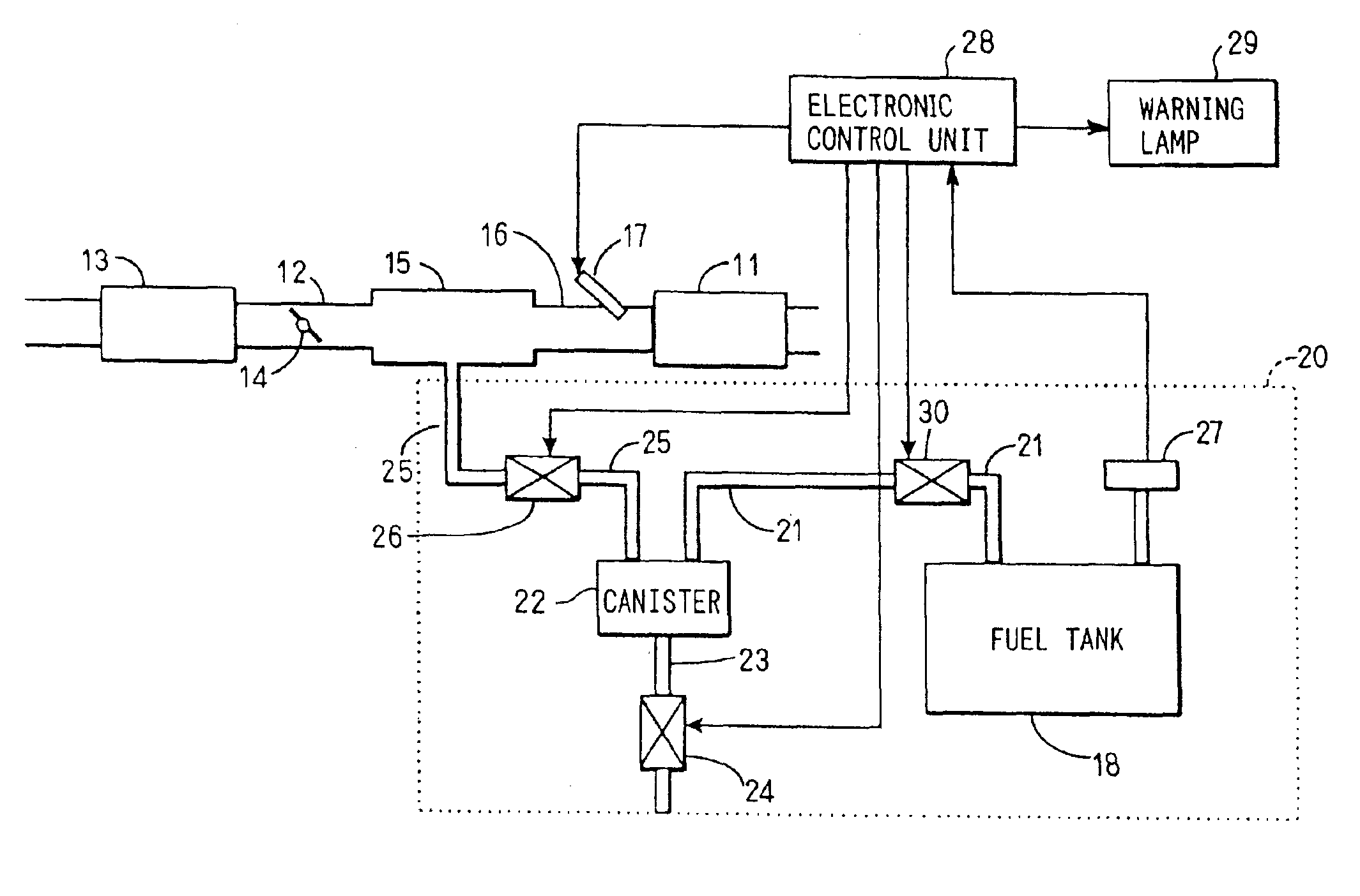
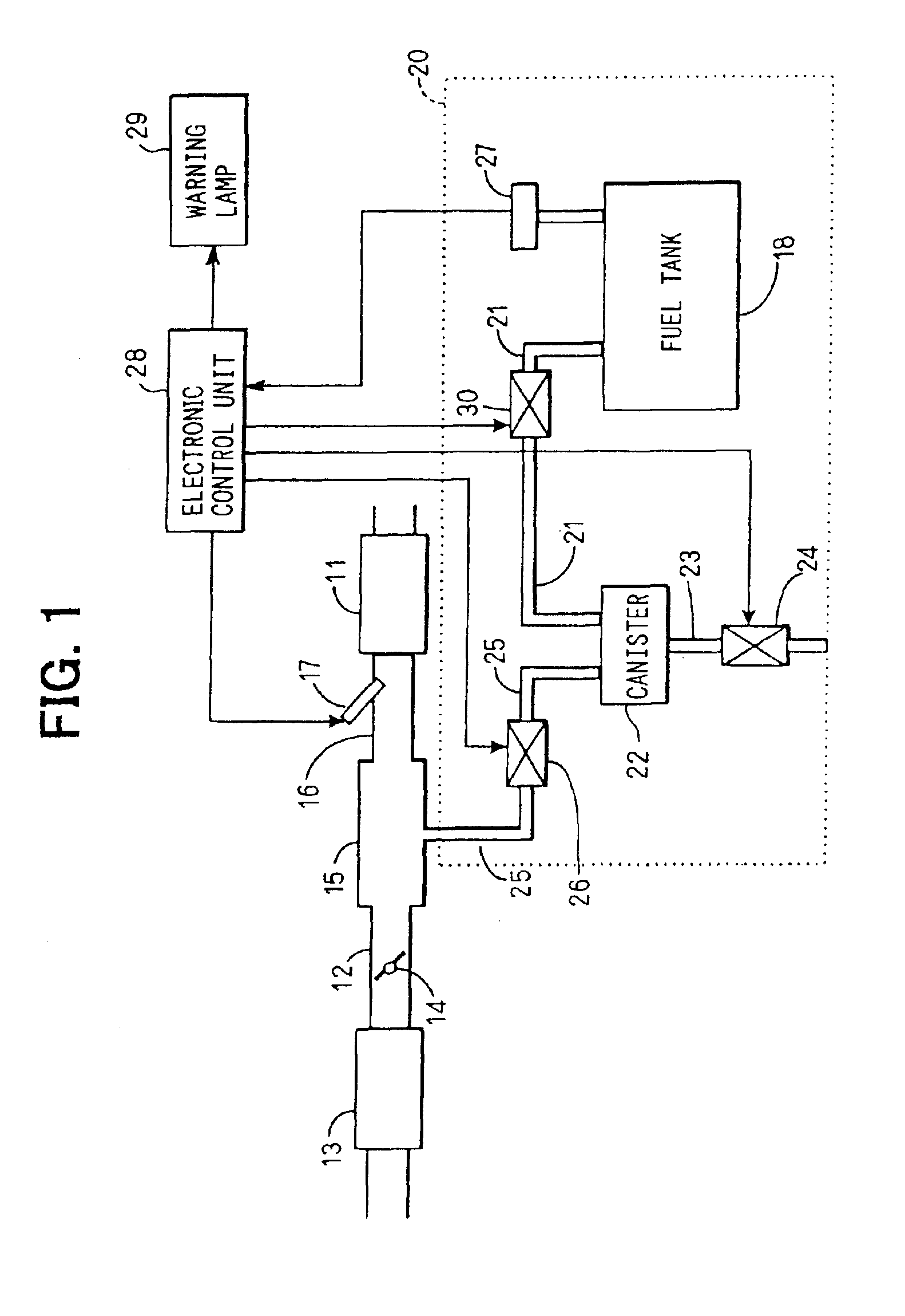
[0048]A first embodiment of the present invention will be described with reference to FIGS. 1-14. First, referring to FIG. 1, an entire structure of a fuel evaporation control system will be described. Outside air is introduced into an internal combustion engine 11 through an air cleaner 13, an intake pipe 12 having a throttle valve 14, a surge tank 15, and an intake manifold 16. A fuel injector 17 is disposed in the intake manifold 16 of each cylinder. Fuel in a fuel tank 18 is sent to the fuel injector 17 through a fuel passage (not shown).

[0049]A fuel evaporation control system 20 is connected to the surge tank 15. A canister 22 is connected to the fuel tank 18 through a vapor passage 21, and a tank-cut valve 30 is disposed in the vapor passage 21. The canister 22 contains activated charcoal for absorbing fuel evaporated from the fuel tank 18. An outlet passage 23 is connected to a bottom hole of the canister 22, and an outlet valve 24 communicating with a...

second embodiment

[0078](Second Embodiment)

[0079]A second embodiment of the present invention will be described with reference to FIGS. 15-25. First, referring to FIG. 15 an entire structure of a fuel evaporation control system will be described. This system is similar to the system shown in FIG. 1, except that a marginal current type air-fuel ratio sensor 31, a three-way catalyzer 32 and an oxygen sensor 33 are disposed in an exhaust pipe 34 of the engine 11. The air-fuel ratio sensor 31 is disposed upstream of the three-way catalyzer 32 and the oxygen sensor 33 is disposed downstream of the three-way catalyzer 32.

[0080]The three-way catalyzer 32 purifies the exhaust gas most effectively when the air-fuel ratio is controlled at a vicinity of a theoretical ratio. The air-fuel ratio detected by the air-fuel ratio sensor 31 is fed to the electronic control unit 28 which controls the air-fuel ratio in the mixture gas supplied to the engine 11 to a vicinity of the theoretical air-fuel ratio under a known...

third embodiment

[0106](Third Embodiment)

[0107]A third embodiment of the present invention will be described with reference to FIGS. 26-29. In this embodiment, the decrease in the air permeability of the canister 22 is detected based on the learned purge gas density Dprg. The learned purge gas density Dprg is detected in two ranges of the amount of purge gas flow PRG. The leaned purge gas density Dprg is continuously renewed based on the air-fuel ratio adjusting factor FAF in the same manner as in the second embodiment.

[0108]A process for detecting the air-permeability decrease in the canister 22 based on the learned purge gas density Dprg will be described with reference to the flowchart shown in FIG. 26. At step S1101, whether detecting conditions are satisfied or not is determined. Since this step is the same as that explained in connection with FIG. 23, the details are not repeated here. If the conditions are not satisfied, the process proceeds to step S1102, where the integrated value of the pu...


PUM


Abstract

A fuel evaporation control system is connected to an engine control system in which an air-fuel ratio in mixture gas supplied to an engine is controlled to an optimum level. Fuel evaporated from a fuel tank is absorbed by a canister, and the absorbed fuel is purged into the engine. Deterioration of the canister in its air-permeability is detected based on measured pressure in the fuel evaporation control system or calculated density in the purge gas, both the pressure and the density being measured or calculated under two different amounts of purge gas flow. Deterioration of the canister in its fuel-absorbing ability is also detected based on the purge gas density.

Description

CROSS-REFERENCE TO RELATED APPLICATIONS[0002]This application is a division of U.S. application Ser. No. 10 / 078,452, filed Feb. 21, 2002, now U.S. Pat. No. 6,564,782.[0003]This application is based upon and claims benefit of priority of Japanese Patent Applications No. 2001-45258 filed on Feb. 21, 2001 and No. 2001-72610 filed on Mar. 14, 2001, the contents of which are incorporated herein by reference.BACKGROUND OF THE INVENTION[0004]1. Field of the Invention[0005]The present invention relates to a fuel evaporation control system for use in an automobile vehicle, and more particularly to a device for detecting deterioration of a canister used in the fuel evaporation control system.[0006]2. Description of Related Art[0007]A fuel evaporation control system in which gaseous fuel evaporated from a fuel tank of an automobile vehicle is absorbed by a canister and the absorbed fuel is purged into an intake pipe of an engine is known hitherto. The canister is composed of activated charcoal...

Claims


Application Information

Patent Timeline
Patent Type & Authority Patents(United States)
IPC IPC(8): F02D41/00F02M25/08
CPCF02D41/0045F02M25/0809F02D41/0042F02D2200/0406F02D2200/0602F02D2041/228
Inventor FUJIMOTO, TAKESHI
Owner DENSO CORP
Features
  • R&D
  • Intellectual Property
  • Life Sciences
  • Materials
  • Tech Scout
  • Unparalleled Data Quality
  • Higher Quality Content
  • 60% Fewer Hallucinations
Learn More