Pathway light fixture

Active Publication Date: 2005-04-05
HUNTER INDUSTRIES
View PDF9 Cites 41 Cited by
  • Summary
  • Abstract
  • Description
  • Claims
  • Application Information

AI Technical Summary

Benefits of technology

It is an advantage of the present invention to provide a pathway light fixture which has a moisture-proof seal to fully enclose the lamp to protect the lamp and socket against exposure to the elements and intrusion by foreign objects.
It is a further advantage of the present invention to provide a pathway light fixture with improved resistance to deterioration by corrosion and oxidation of the materials of which the fixture is made.
Another advantage of the present invention is to provide a pathway light fixture which is easily assembled and disassembled while retaining its moisture-proof seal.
In an exemplary embodiment, the pathway light fixture for outdoor installation comprises a stem, a socket assembly disposed in the top of the stem for retaining a halogen lamp, a lens support, a diffuser and a reflector top. The lens support is formed with a generally conical outer shape and an annular recess that is dimensioned to receive the outer diameter of the socket assembly. The recess in the lens support is slightly tapered so that it has a larger diameter at its lower end. The cylindrical diffuser is retained in an annular channel formed in the upper surface of the lens support, where it is sealed with a silicone, epoxy or other water-tight sealant. The flared reflector has a cylindrical portion which fits closely over the top of the diffuser lens where it is sealed using silicone, epoxy or other sealant to protect the internal sur

Problems solved by technology

Outdoor light fixtures are prone to dirt build-up and/or corrosion which can diminish light output and accelerate deterioration and, ultimately, failure of the fixture.
However, the lamp and socket remain exposed and, therefore, can deteriorate with time, interfering with the lamp and socket connection.
However, in closed fixture designs, one must disassemble the housing to access the lamp for replacement.
Where metal-to-metal contact occurs in the enclosure seal, the built-up dirt and/or corrosion can act to “weld” the connectio

Method used


Image

  • Pathway light fixture
  • Pathway light fixture
  • Pathway light fixture

Examples


Embodiment Construction

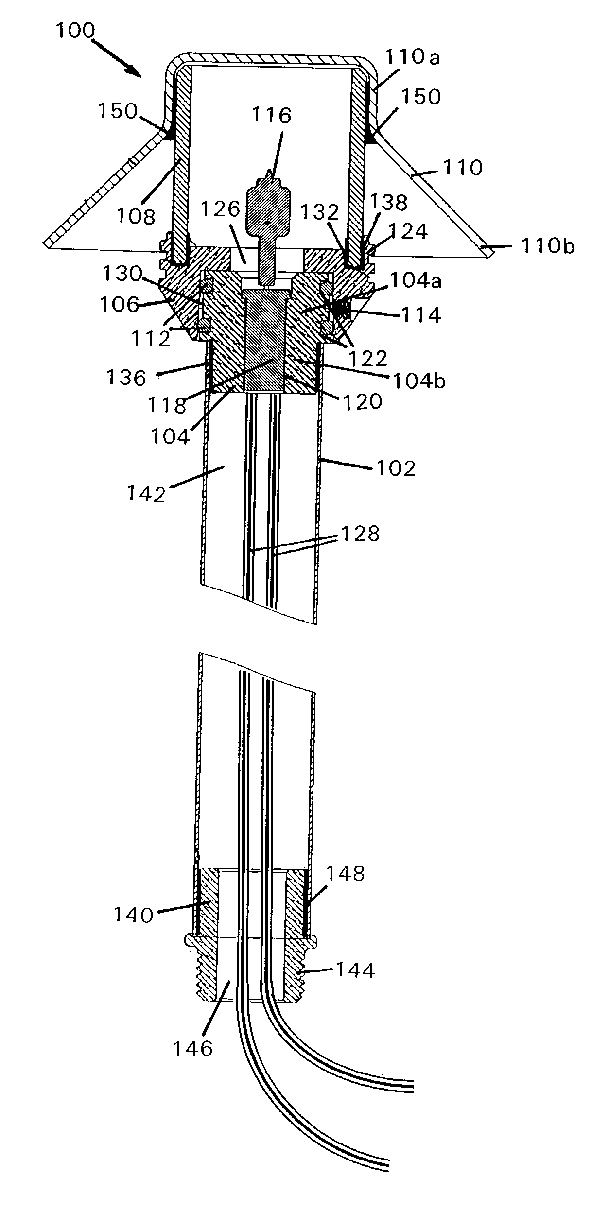
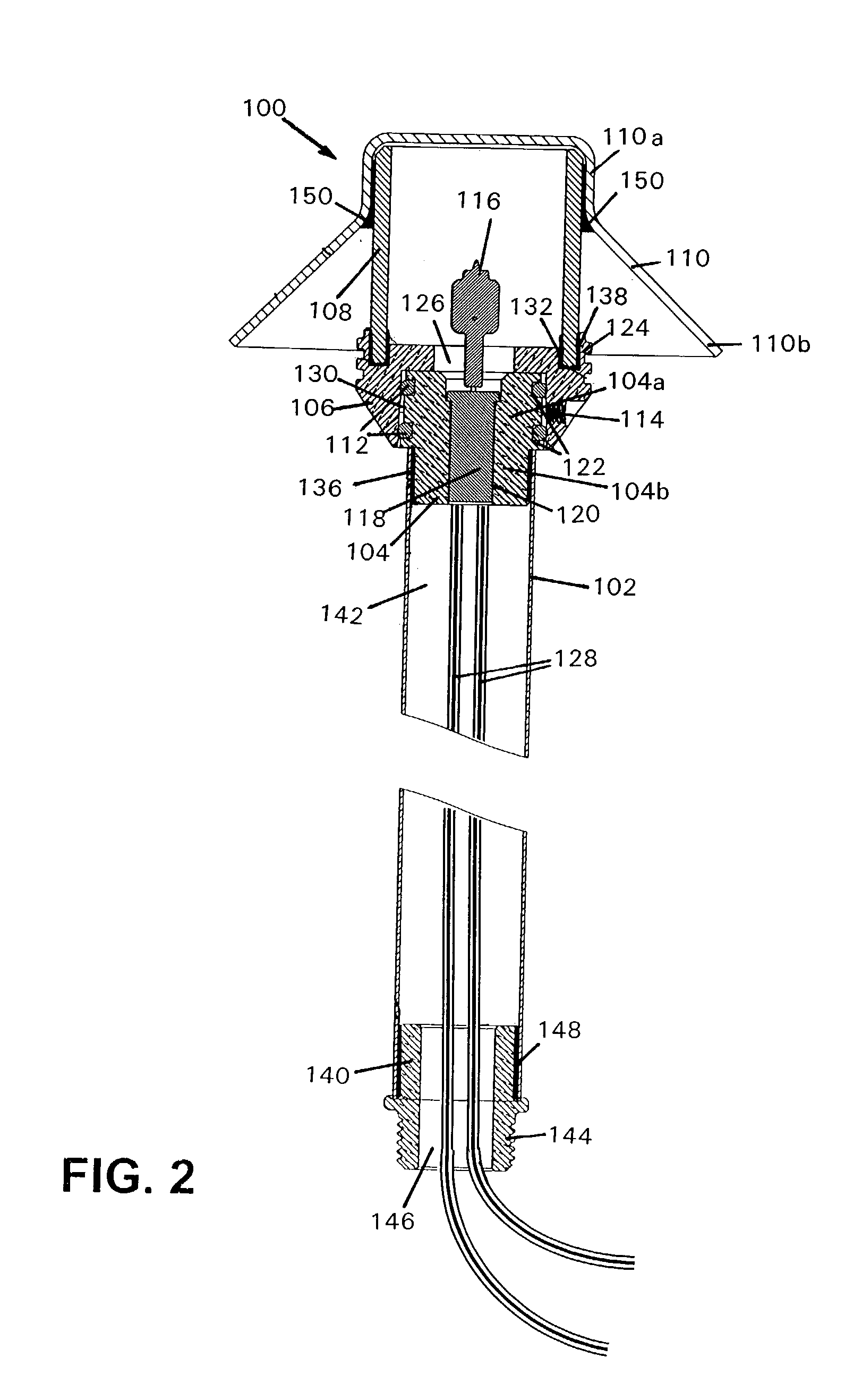
FIG. 1 illustrates a pathway lighting fixture generally designated by reference numeral 100. The lighting fixture 100 includes a stem in the form of a generally elongated tubular post 102 with a first end and a second end, the first end to which is attached to the lower end of the socket housing 104, and a lens assembly, which encloses the electrical components in a moisture-proof enclosure, comprising a cylindrically-shaped diffuser lens 108 (not visible in FIG. 1) disposed in the upper end of lens support 106, and a symmetrically flared reflector 110. Post 102 and reflector 110 should be made of a durable and aesthetically pleasing material. In the preferred embodiment, post 102 and reflector 110 are formed from solid copper, which is intended to oxidize to a verde finish and, thus, is preferably uncoated. Other corrosion resistant materials may be used as well, including stainless steel, anodized aluminum, powder-coated or painted metal, or high temperature plastics or composites...


PUM


Abstract

A light fixture for use in low voltage outdoor lighting systems that comprises a lens assembly with a reflector, lens and lens support and a socket assembly with a lamp, socket and socket housing, which are mounted on a post. Connection of the lens assembly and socket assembly is provided by the combination of a taper fit and multiple O-rings which provide a frictional fit that is sealed against dirt and moisture intrusion, avoiding metal-to-metal contact. Attachment of the lens assembly to the socket assembly is achieved by pressing the two parts together in an axial direction. Disassembly is achieved by twisting to overcome the friction generated by the O-rings and pulling the two assemblies apart. A locking screw may be used to prevent accidental separation of the lens assembly and socket assembly. The post can be attached to a ground spike for installation.

Description

FIELD OF THE INVENTION The invention relates to a light fixture for use in low voltage outdoor lighting systems and more specifically to a pathway light fixture which is readily assembled and disassembled. BACKGROUND OF THE INVENTION Environmental lighting, particularly outdoor lighting, is well known in commercial or public settings, such as parks and schools. Such lighting is also popular in residential applications, both to enhance the appearance and safety of the outdoor area and for security, to illuminate dark areas around a building or in a yard which may provide hiding places and unobserved entry points for intruders. Landscape and outdoor lighting systems include one or more lighting fixtures which are connected to either a 12 V transformer or a standard 120 VAC line. Some lighting fixtures enclose a halogen lamp or conventional bulb within a housing, and include a reflector assembly and a lens or window. These fixtures may be used for highlighting features such as trees or...

Claims


Application Information

Patent Timeline
IPC IPC(8): F21V21/116F21V21/10F21S8/00F21S8/08F21V27/00F21V17/00F21V31/00
CPCF21S8/081F21V21/0824F21V21/116F21V31/005F21W2131/109F21W2131/10F21V27/00
Inventor BEADLE, JOSHUA Z.
Owner HUNTER INDUSTRIES
Why Eureka
Try Eureka