Blade for resection of bone for prosthesis implantation, blade stop and method

a bone resection and prosthesis technology, applied in the field of orthopaedics, can solve the problems of difficult control of the depth of the cut, inability to perform joint replacement surgery, and difficulty in reducing so as to reduce the number of other instruments, the effect of accurate cut depth and easy adjustment of the stop

Inactive Publication Date: 2005-04-05
DEPUY PROD INC
View PDF16 Cites 127 Cited by
  • Summary
  • Abstract
  • Description
  • Claims
  • Application Information

AI Technical Summary

Benefits of technology

The technical advantage of the present invention also includes the ability to use fewer instruments in an instrument set. For example, according to the present invention, the stop on the blade may be adjusted. Thus a blade may be utilized having many different stops. An alternative approach may have been to provide for a series of blades, each blade having a different fixed stop. Utilizing a system with blades having various different stops, require a large number of blades to be included in the instrument set.
also includes the ability to use fewer instruments in an instrument set. For example, according to the present invention, the stop on the blade may be adjusted. Thus a blade may be utilized having many different stops. An alternative approach may have been to provide for a series of blades, each blade having a different fixed stop. Utilizing a system with blades having various different stops, require a large number of blades to be included in the instrument set.
The technical advantage of the present invention also includes the ability to lessen the number of other instruments in, for example, the form of retractors that may otherwise be required to be used to protect the anatomy from saw cuts. For example, retractors are used between the saw and critical elements of soft tissue, for example, in total ankle arthroplasty, the Achilles tendon. The adjustable stop of the surgical blade of the present invention used in conjunction with a saw block will provide for an accurate depth of cut, such that the use of retractors to protect soft tissue may not be necessary.
The technical advantage of the present inventions may also include the ability of the stop to not catch the edge of the saw block. This feature is provided by providing the stop with a round front face that represents the arc of the oscillating motion.
According to another aspect of the present invention, the stop may slide up and down the blade providing for easy adjustment of the stop. Further, the stop may feature for quick release of the stop at each position of the blade.
By providing the scaled hash marks, the position of the stop on the surgical blade can be very easily determined.

Problems solved by technology

Joint replacement surgery is quite common and it enables many individuals to function properly when otherwise it would not be possible to do so.
Such patients of joint replacement surgery typically suffer from osteoarthritis or rheumatoid arthritis.
When sawing through a saw block with an oscillating saw, it is difficult to control the depth of the cut.
When utilizing an oscillating saw to resect bone, as the saw penetrates completely through the bone, the force required to cut through the hard bone may cause the saw to lunge forward toward the soft tissue.
Such scales do not actually stop the blade from cutting too deep and damaging soft tissue, ligaments or tendons.

Method used


Image

  • Blade for resection of bone for prosthesis implantation, blade stop and method
  • Blade for resection of bone for prosthesis implantation, blade stop and method
  • Blade for resection of bone for prosthesis implantation, blade stop and method

Examples


Embodiment Construction

Embodiments of the present invention and the advantages thereof are best understood by referring to the following descriptions and drawings, wherein like numerals are used for like and corresponding parts of the drawings.

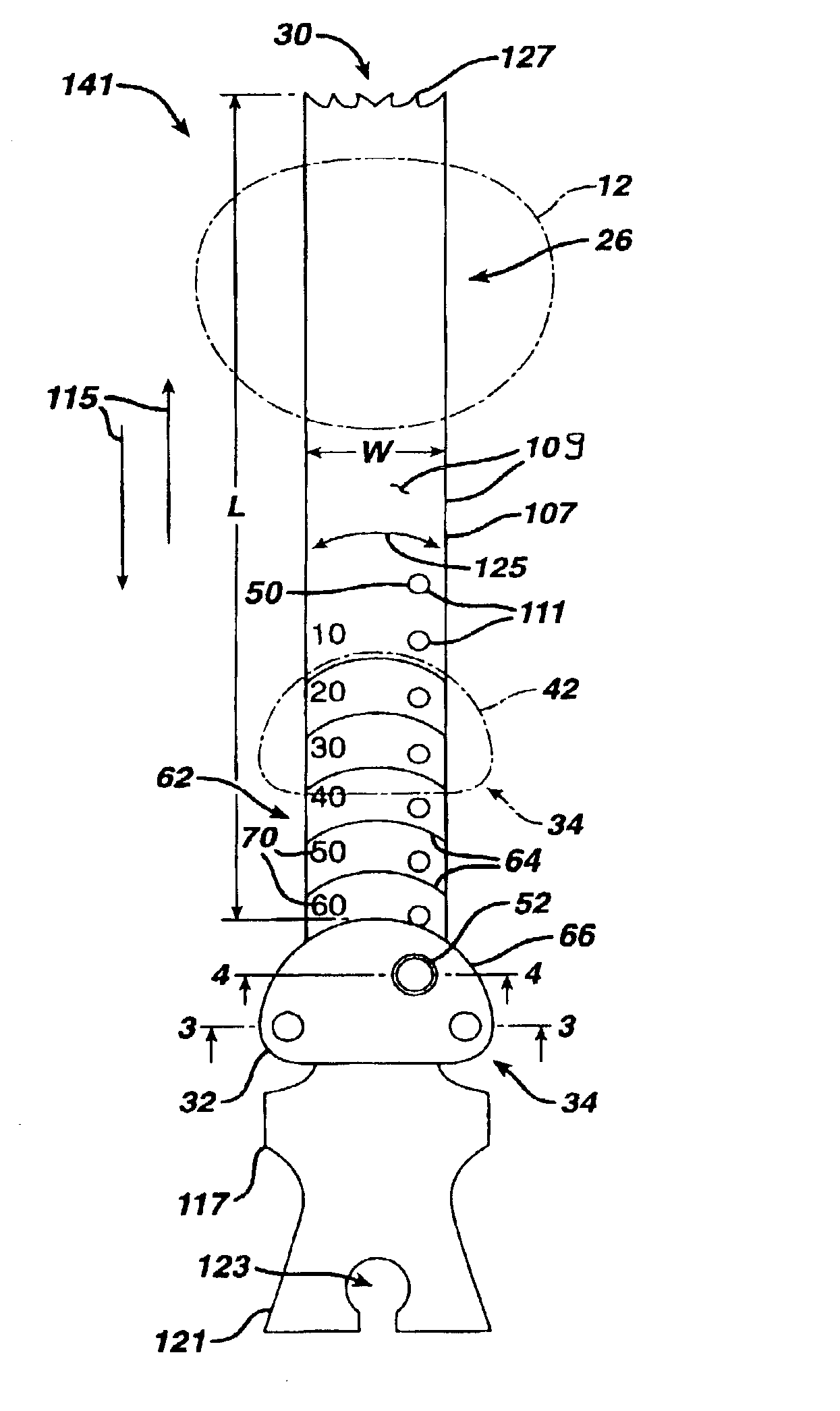
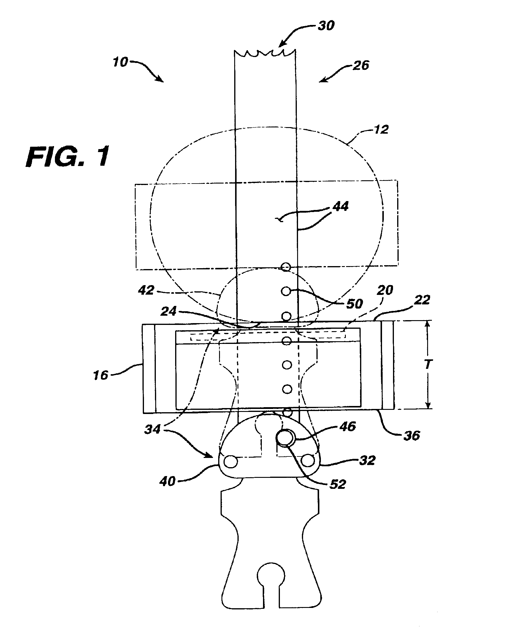
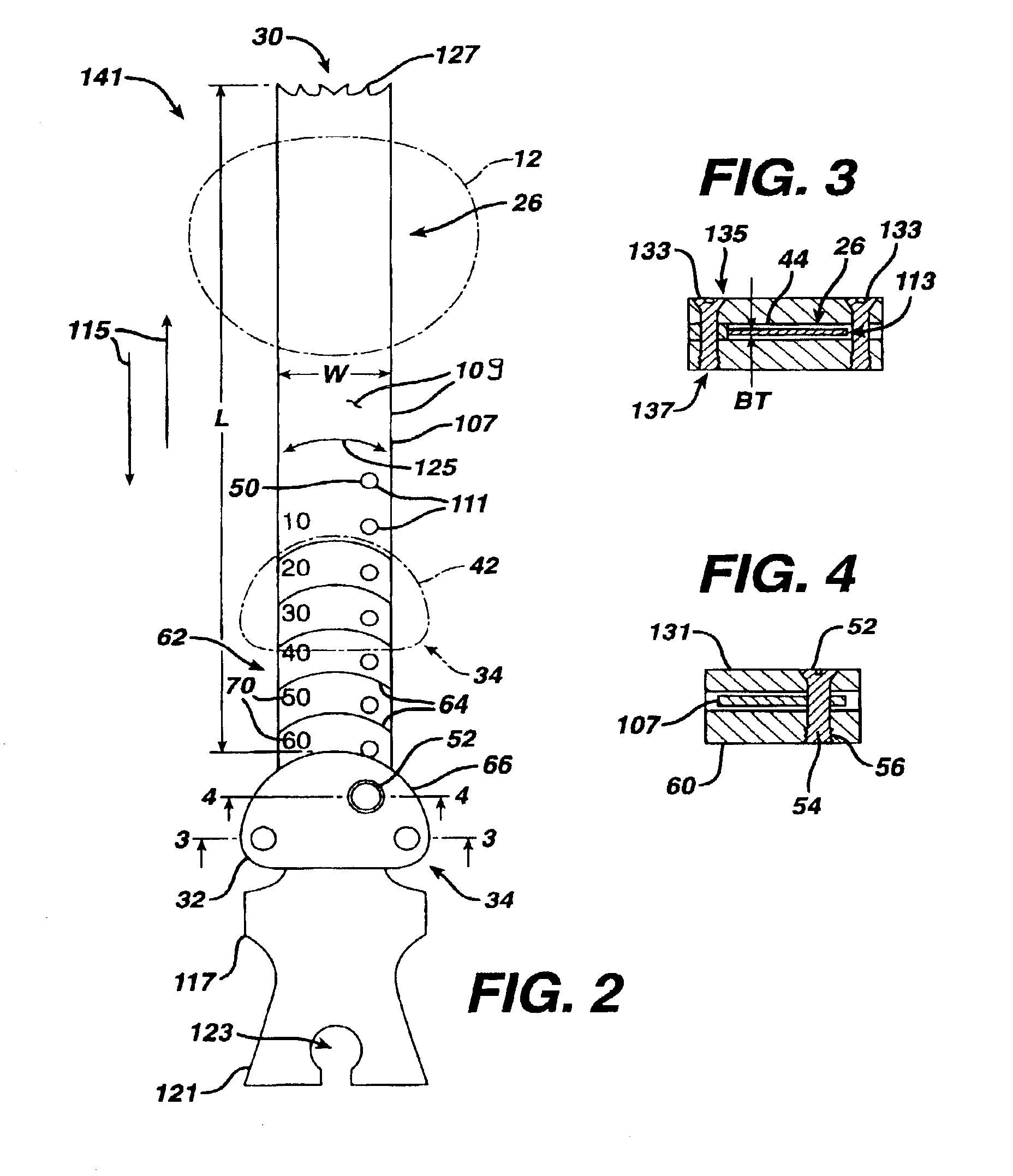
According to the present invention and referring to FIG. 1, a kit 10 is shown. The kit 10 is utilized for resection of bone 12 to prepare the bone 12 for the implantation of a joint prosthesis 14 (see FIG. 9). The kit 10 includes a guide 16.

The guide 16 defines an opening 20 through the guide 16. The guide 16 is in cooperation with the bone 12, for example and as shown in FIG. 1, the guide 16 includes a first surface 22 which is in contact with surface 24 of bone 12. The kit 10 further includes a tool 26.

Referring now to FIG. 5, the tool 26 is constrainable within the opening 20 of the guide 16. Referring again to FIG. 1, the tool 26 includes a cutting edge 30 adapted for resection of bone 12.

The kit 10 further includes a stop 32 cooperable with the guide 16 and the...


PUM

PropertyMeasurementUnit
thicknessaaaaaaaaaa
thicknessaaaaaaaaaa
distanceaaaaaaaaaa

Abstract

A kit (10) for resection of bone (12) for use in implantation of a joint prosthesis (14) is provided. The kit (10) includes a guide (16), a tool (26) and a stop (32). The guide (16) defines an opening (20) through the guide (16). The guide (16) is in cooperation with the bone (12). The tool (26) may be constrained within the opening (20) of the guide (16). The tool (26) includes a cutting edge (30) for resection of bone (12). The stop (32) cooperates with the guide (16) and the tool (26) to limit the movement of the tool (26) within the guide (16) so that the position of the cutting edge (30) with respect to the bone (12)m may be controlled. The stop (32) includes a plurality of positions (34) with respect to the tool (26) and the guide (16).

Description

TECHNICAL FIELD OF THE INVENTIONThe present invention relates generally to the field of orthopedics, and more particularly, to an implant for use in arthroplasty.BACKGROUND OF THE INVENTIONJoint replacement surgery is quite common and it enables many individuals to function properly when otherwise it would not be possible to do so. Such patients of joint replacement surgery typically suffer from osteoarthritis or rheumatoid arthritis. Artificial joints usually comprise metallic, ceramic and / or plastic components that are fixed to existing bone.Such joint replacement surgery is otherwise known as total joint arthroplasty. Total joint arthroplasty is a well known surgical procedure by which a diseased and / or damaged joint is replaced with a prosthetic joint. In a typical total joint arthroplasty, the ends or distal portions of the portion of the bone adjacent the joint are resected or a portion of the distal part of the bone is removed and the artificial joint is secured thereto. Ofte...

Claims


Application Information

Patent Timeline
Patent Type & Authority Patents(United States)
IPC IPC(8): A61B17/32A61B17/16A61B17/58B23D47/02B23D47/00A61B17/14A61B17/15A61B19/00
CPCA61B17/14A61B17/148A61B17/141A61B17/154A61B2019/304A61B17/15A61B2090/034A61B17/142
Inventor LONG, JACK F.MARONEY, BRIAN JOHNSANDERS, ROYCORDES, KEVIN M.FISHER, MICHAEL G.
Owner DEPUY PROD INC
Why Eureka
Try Eureka