
Driving instrument with variably angled joint and extended tip and method of use for minimally invasive hip surgery

a technology of hip joint and driving instrument, which is applied in the field of performing minimally invasive hip replacement surgery, can solve the problems of longer rehabilitation time for patients, increased blood loss, and further damage to the hip joint and surrounding soft tissue, so as to reduce the cost of both patient and hospital, and the effect of shortening the incision and prolonging the incision

Inactive Publication Date: 2005-04-05
ZIMMER INC
View PDF6 Cites 55 Cited by
  • Summary
  • Abstract
  • Description
  • Claims
  • Application Information

AI Technical Summary

Benefits of technology

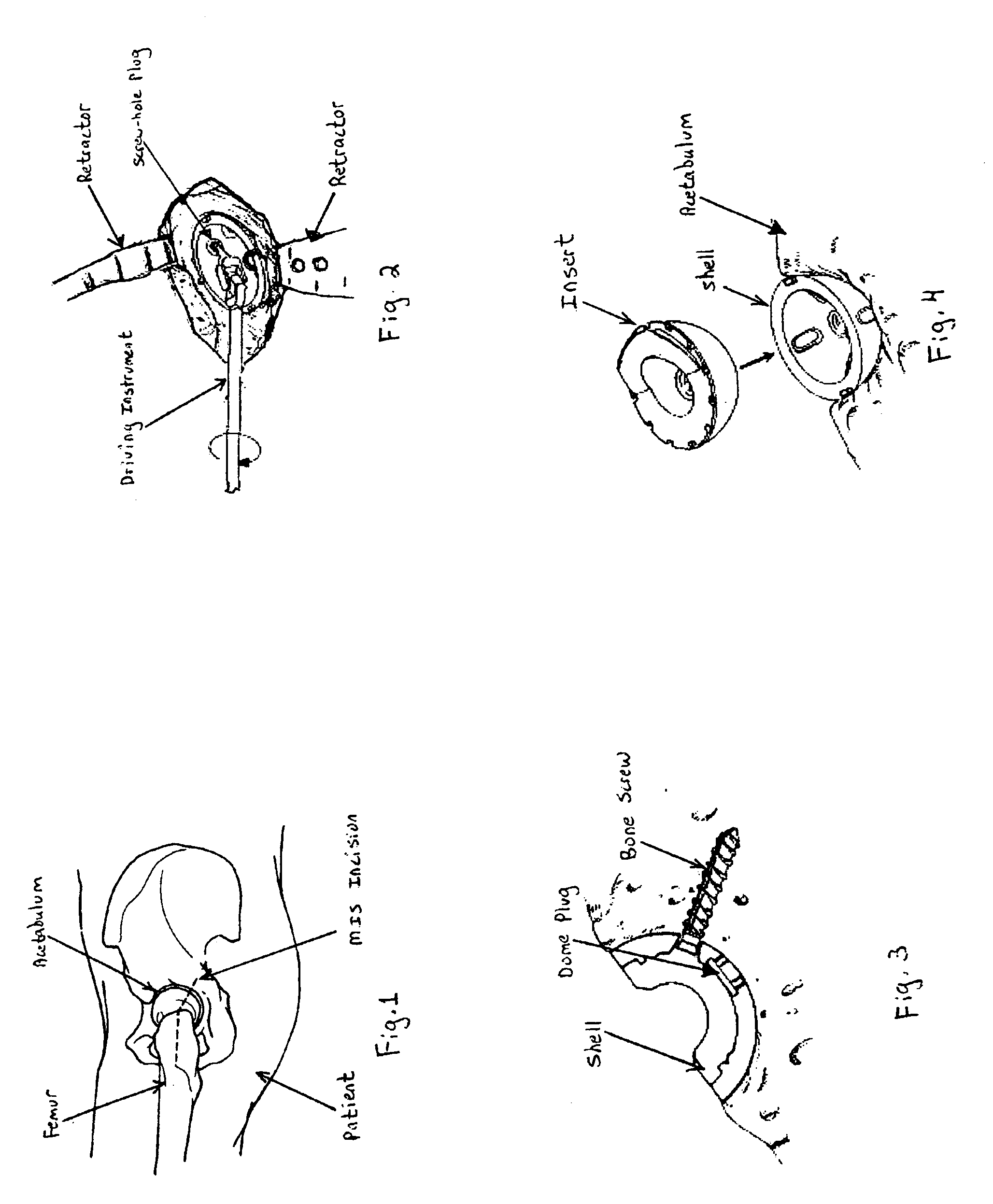
One important advantage of the present invention is that the method and driving instrument are used in a minimally invasive orthopedic hip surgery. A single, small three to five inch incision is made at the surgical site on the side on the hip. The method of the present invention, thus, enjoys the benefits of a shorter incision compared to traditional hip surgery that uses a much longer incision. As one benefit, the patient can recover in a much shorter period of time after a MIS. The recuperation time in the hospital can be a few days and significantly reduce the cost to both the patient and hospital. This shortened time period is extremely important to the patient. Further, MIS is less invasive and traumatic to the patient. Significantly less soft tissue is disrupted in a minimally invasive surgery compared to a traditional hip surgery. Also, the amount of blood loss is reduced, and patients will require fewer blood transfusions. Further, the length of the scar is significantly smaller, and these scars are more cosmetically appealing. The incisions themselves heal in a much shorter period of time and are much less painful than a long ten or twelve inch incision. As such, the patient can sooner return to work or enjoy recreational activities. In short, the patient can more quickly return to a normal way of life.
is that the method and driving instrument are used in a minimally invasive orthopedic hip surgery. A single, small three to five inch incision is made at the surgical site on the side on the hip. The method of the present invention, thus, enjoys the benefits of a shorter incision compared to traditional hip surgery that uses a much longer incision. As one benefit, the patient can recover in a much shorter period of time after a MIS. The recuperation time in the hospital can be a few days and significantly reduce the cost to both the patient and hospital. This shortened time period is extremely important to the patient. Further, MIS is less invasive and traumatic to the patient. Significantly less soft tissue is disrupted in a minimally invasive surgery compared to a traditional hip surgery. Also, the amount of blood loss is reduced, and patients will require fewer blood transfusions. Further, the length of the scar is significantly smaller, and these scars are more cosmetically appealing. The incisions themselves heal in a much shorter period of time and are much less painful than a long ten or twelve inch incision. As such, the patient can sooner return to work or enjoy recreational activities. In short, the patient can more quickly return to a normal way of life.
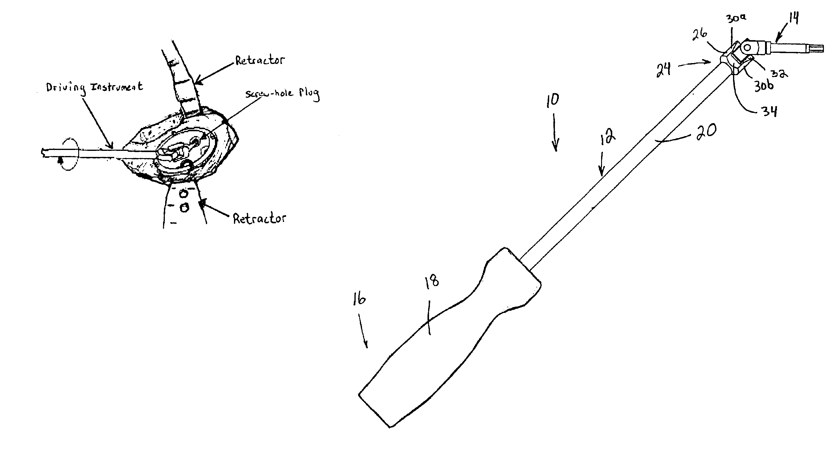
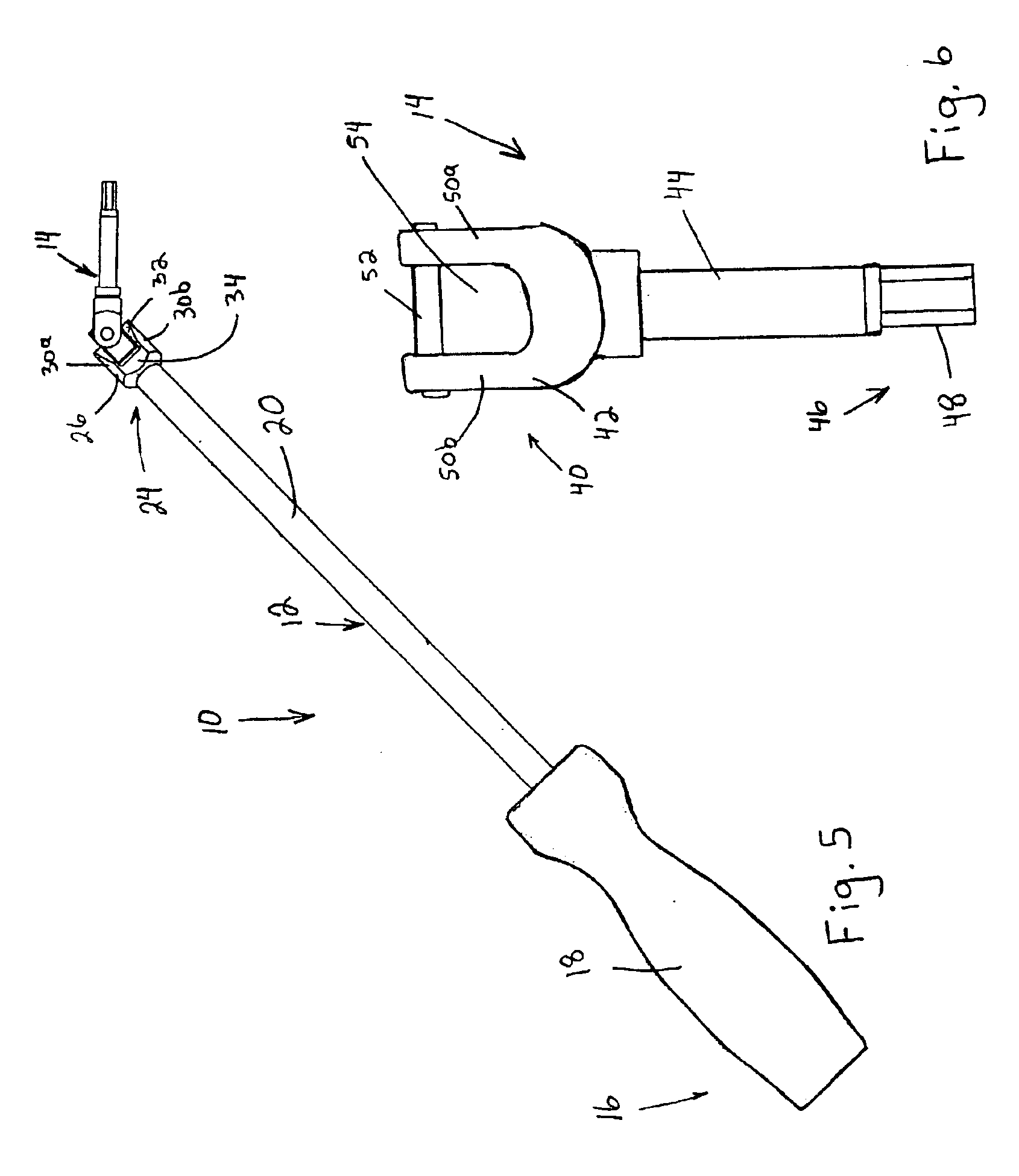
Another important advantage of the present invention is that the driving instrument uses a variably angled joint connector. The driving instrument can drive a screw-hole plug or bone screw while the working section and driving section are at various angles to each other. The various angles between the working and driving sections and the size and shape of the driving instrument are specifically designed and adapted to be used in minimally invasive surgical techniques for aligning and driving screw-hole plugs and bone screws into a prosthetic acetabular shell.
Another important advantage of the present invention is that the various angulations of the driving section of the driving instrument keep the handle away from the entrance to the surgical site. In MIS, it is particularly important to maintain a clear and unobstructed access to the surgical site since it is so small, measuring approximately 3-5 inches in length. Further, it is important not to disrupt or aggravate the sides of the wound channel during the surgical procedure. In the present invention, the handle and working section extend outwardly and away from the sides of the surgical site. The instrument, thus, can be used without unnecessarily disrupting or aggravating the surgical site.
As a further advantage, the handle and working section can be easily maneuvered through various angles around the surgical site while the driving section drives a screw-hole plug or bone screw into the acetabular shell. The surgeon can manipulate or move the handle to obtain a desired angle for driving the screw-hole plugs and bone screws. The handle, for example, can be moved to provide a better angle for driving the plug and screw or moved to provide a better angle for observing into the surgical site.
The driving instrument generally comprises a body having two primary sections, a working section and a driving section. The working section includes a handle at a proximal end and an elongated shaft connected to a working head portion at a distal end. The driving section has a driving head at a proximal end, a drive shaft extending from the head, and a driving tip at a distal end. This driving tip is shaped and sized to engage a screw-hole plug or bone screw and carry this plug or screw to the acetabular shell embedded in the natural acetabulum. The screw or plug can then be driven into the acetabular shell with the driving instrument. A joint connector connects the working head of the working section to the driving head of the driving section. This joint enables the working section to rotate the driving section while the two sections are disposed at an angle with respect to each other. Preferably, the joint connector is U-joint connector that offers variable angulations between the working section and driving section. A driving guide may be attached to the driving tip of the driving section. The driving guide helps align and guide the driving instrument while a screw-hole plug or bone screw is inserted into the acetabular shell. The driving instrument is discussed in more detail with reference to the figures.

Problems solved by technology

Unfortunately, traditional techniques to implant a hip have well recognized shortcomings.
A long, deep incision can divide a number of important stabilizing muscles and tendons and further damage the hip joint and surrounding soft tissue.
Inevitably, long incisions lead to larger blood losses, longer rehabilitation times for patients, and unsightly scar lines.
If the implant is not accurately placed, then complications, such as dislocation or subluxation, can occur.
A successful design of instruments for MIS has other challenges as well.
If the MIS instrumentation is too cumbersome or not easy to manipulate, then the surgeon will be less likely to use minimally invasive surgery.
If, for example, the instruments are too complex and complicated, then they will not be appealing and accepted in the orthopedic surgical community.
Further yet, the training and skill level required to use the instruments and become proficient with them, cannot be overly taxing on the orthopedic surgeons.
Traditional surgical driving instruments, though, are not shaped and sized to engage a screw-hole plug or bone screw and place it through the acetabular shell.
Thus, a straight driving instrument will not have the proper angulation to reach the screw-hole opening in the shell.
If the bone screw is not placed with the correct angle, then the bone screw may not seat well in the screw-hole opening.
Additionally, the bone screw may not properly engage cortical bone to hold the shell in place in the acetabulum.

Method used


Image

  • Driving instrument with variably angled joint and extended tip and method of use for minimally invasive hip surgery
  • Driving instrument with variably angled joint and extended tip and method of use for minimally invasive hip surgery
  • Driving instrument with variably angled joint and extended tip and method of use for minimally invasive hip surgery

Examples


Embodiment Construction

The instruments, method, and steps of the present invention are now described in more detail. The method describes the steps to perform a minimally invasive surgery to implant a prosthetic acetabular component into the natural acetabulum of a patient. Some of these steps described in the method are known to those skilled in the art and will not be discussed in great detail. Further, one skilled in the art will appreciate that certain steps may be altered or omitted while other steps may be added without departing from the scope of the invention. The novel steps of the present invention, for example, can be applied to total hip arthroplasty, to revision surgeries for total and partial hip replacement, and to other orthopedic hip surgeries using minimally invasive surgical techniques.

To facilitate a discussion of the present invention, the method of implanting a prosthetic acetabular component is divided into a plurality of steps or sections. Each of these sections is discussed seriat...


PUM


Abstract

A method and apparatus for performing minimally invasive hip surgery for implanting a prosthetic acetabular component into a natural acetabulum. The method and apparatus include a driving instrument and driving guide for aligning and driving bone screws and screw-hole plugs. The instrument includes a working section and a driving section connected together with a joint connector. The joint connector enables the working and driving sections to move to various angles relative to each other.

Description

FIELD OF THE INVENTIONThe disclosure herein generally relates to a method and apparatus for performing minimally invasive hip replacement surgery for the acetabulum using a driving instrument with a variably angled joint and extended tip.BACKGROUND OF THE INVENTIONTraditional hip replacement surgery has been used in the United States since as early as the 1960's. The surgical technique to implant a hip has not drastically changed over the years, and today, this technique is quite successful. In fact, the surgical technique is prolifically used throughout the world and has a known success rate of over 90%. Certainly, the traditional surgical technique is fundamentally sound and predictable.Unfortunately, traditional techniques to implant a hip have well recognized shortcomings. Most importantly, a rather large incision is made on the side of the hip. The incision can extend from 6 to 12 inches; the actual length of the incision depends on the size of the patient and type of surgery (...

Claims


Application Information

Patent Timeline
IPC IPC(8): A61B17/17A61B17/16A61B17/88A61B17/00A61B17/86A61F2/00A61F2/02A61F2/30A61F2/34A61F2/46
CPCA61B17/1746A61B17/8875A61F2/34A61F2/4609A61F2/4637A61B17/00234A61F2250/0006A61B17/86A61B2017/00464A61F2/30744A61F2/4684A61F2002/30487A61F2002/30538A61F2002/30774A61F2002/30777A61F2002/30787A61F2002/3401A61F2002/3404A61F2002/3411A61F2002/3443A61F2002/4623A61F2002/4629A61F2002/4635A61F2002/4638A61F2002/464A61F2002/4641A61F2002/4681A61F2220/0025A61B17/1735A61F2/4603A61F2002/305A61F2002/3403
Inventor DYE, DONALD
Owner ZIMMER INC
Learn More