
Neovascularization promoting membrane for bioimplants

a bioimplant and promoting membrane technology, applied in the field of bioimplants, can solve the problems of reducing the output, affecting the effect of the implant, and the sensor cannot measure the level of the analyte, and the foreign body reacts with the resultant isolation of the implant from bodily tissues and fluids

Inactive Publication Date: 2005-04-05
WAVEFORM TECH INC
View PDF8 Cites 244 Cited by
  • Summary
  • Abstract
  • Description
  • Claims
  • Application Information

AI Technical Summary

Benefits of technology

The foregoing and other objectives, features, and advantages of the inve

Problems solved by technology

With certain types of implants, notably electrical leads and biosensors, the foreign body reaction with its resultant isolation of the implant from bodily tissues and fluids, is detrimental.
In the case of an electrical lead for stimulating tissue, the presence of a fibrotic capsule surrounding the lead dampens and decreases the output of the lead.
If an avascular fibrous capsule prevents the analyte from reaching the sensor, the sensor can no longer measure the level of the analyte even though the sensor itself is functioning properly.
Increasing the sensitivity of the sensor, although somewhat analogous to increasing the voltage of an implanted electrical lead, does not correct the problem if the sensor is sealed off from tissue fluid containing the analyte.
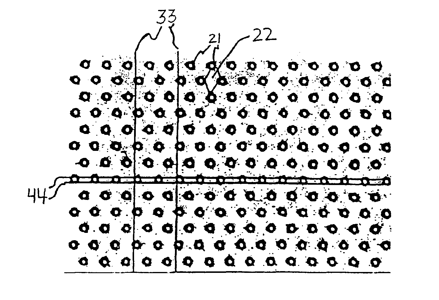
Although with salt crystal poration and neutron bombardment the pore sizes are quite uniform, nonuniform pore spacing results in an unpredictable structure with an unpredictable tendency to promote neovascularization.
The variability of pore size and distribution in presently available membranes results in unpredictability of the foreign body reaction that is elicited by implantation of such membranes.
Additionally, although biological electricity sensors have been disclosed that included a microporous membrane covering the sensing surfaces, it appears that no similar analyte sensor has been taught.

Method used


Image

  • Neovascularization promoting membrane for bioimplants
  • Neovascularization promoting membrane for bioimplants
  • Neovascularization promoting membrane for bioimplants

Examples


example 1

Uncoated (Prior Art) Bioimplants

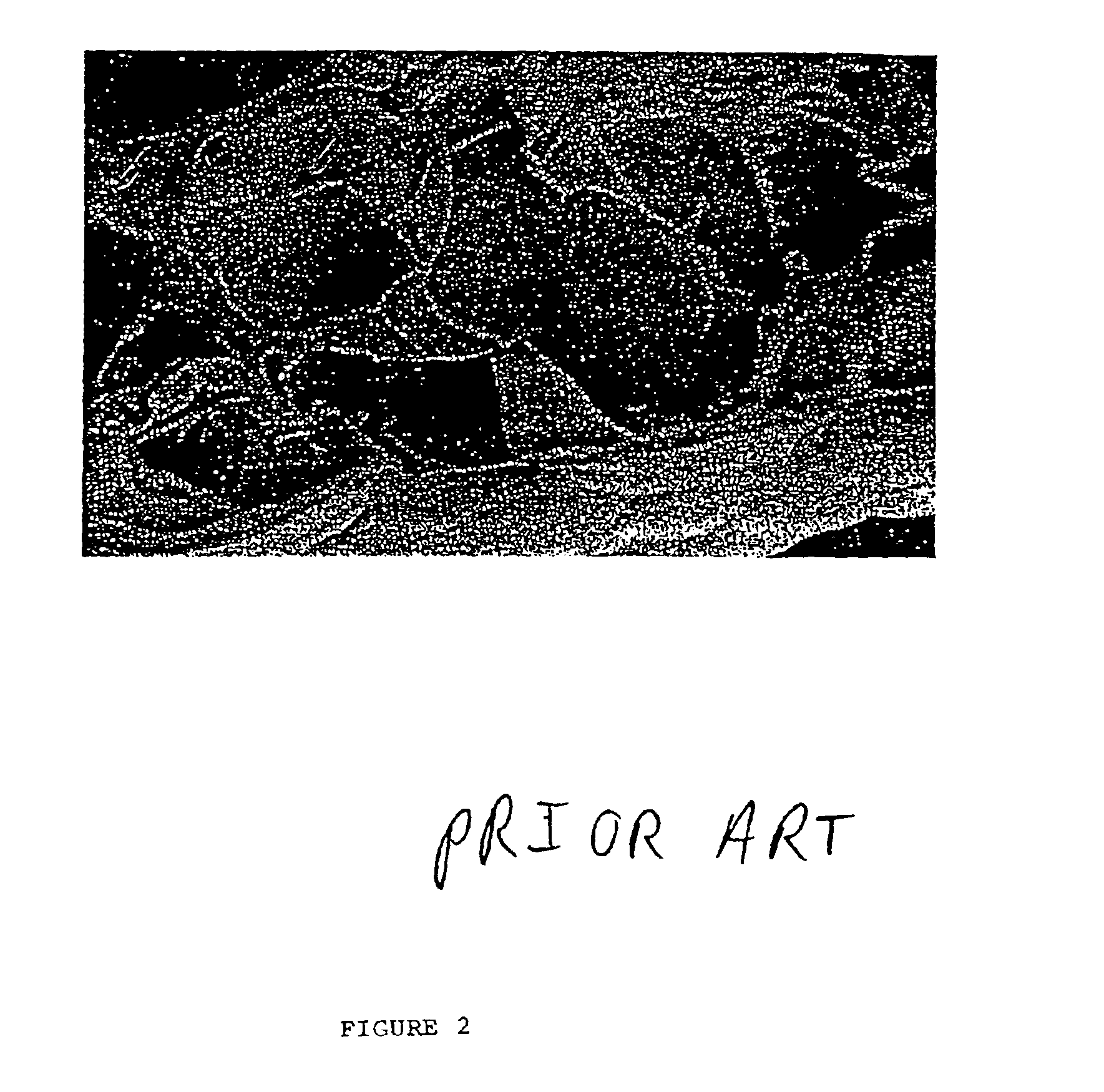
One-centimeter segments of a 20 gauge PTFE catheter were implanted in the subcutaneous tissues of a rat. After five weeks, the catheters and surrounding tissues were removed and examined microscopically, as shown in FIG. 5. The photomicrograph of FIG. 5 shows a well-defined dense collagen capsule 41 about 35 micrometers in thickness and having substantially parallel oriented fibers between the PTFE device 42 and the surrounding loose connective tissue 43. Two cells 44 are visible at the junction of the catheter and the fibrous capsule.

example 2

Bioimplants Coated in Accordance with the Invention

One centimeter segments of PTFE catheters as in Example 1 were wrapped with a porous cellulose acetate membrane in which substantially uniform 5 micrometer pores having a substantially uniform interpore distance of 20 micrometers were laser-machined. After 5 weeks, the catheter and surrounding tissues were removed from the rat and examined microscopically, as shown in FIG. 6. The photomicrograph of FIG. 6 shows loose connective tissue 51 extending to the border of the PTFE catheter 52. A fibrous foreign body capsule was not detected, indicating that the microporous membrane surrounding the implant prevented, or at least greatly reduced, the formation of a foreign body capsule around the implant.


PUM

PropertyMeasurementUnit
Lengthaaaaaaaaaa
Areaaaaaaaaaaa
Energyaaaaaaaaaa

Abstract

A method of producing a biocompatible microporous membrane comprising the steps of providing a biocompatible membrane and using an energy beam to form a set of pores having a minor axis of less than 15 μm through the biocompatible membrane. One embodiment includes the steps of producing a first layer of material, defining a first set of pores; producing a second layer of material, defining a second set of pores and wherein the second set of pores is defined so as to cooperatively engage the first set of pores; and aligning and joining the first layer of material to the second layer of material to form a laminated membrane, having through-passageways formed by the first set of pores at least partially aligned with the second set of pores.

Description

FIELD OF THE INVENTIONThe present invention pertains to the field of bioimplants, particularly to the field of preventing foreign body reactions, especially fibrosis, around bioimplants. In a particular embodiment, the invention pertains to the field of prolonging the useful life of an implanted biosensor by reducing or eliminating the fibrous capsule that results from the body's response to the presence of the implant.BACKGROUND OF THE INVENTIONMaterials are implanted into a human or animal body for a variety of purposes. Such implants include prosthetic devices, electrical leads, vascular grafts, and biosensors. Generally, most implants provoke a classic foreign body reaction. This reaction includes an acute inflammatory response of inflammatory cells and fibroblasts followed by a decrease in the acute inflammatory reaction and the production of a collagen. Eventually, the fibroblasts mature into fibrocytes, an avascular fibrous capsule is formed which walls off the implant, and t...

Claims


Application Information

Patent Timeline
IPC IPC(8): A61L29/08A61L29/14A61L31/10A61L31/14B23K26/38
CPCA61L29/085A61L29/14A61L29/146B23K26/4065A61L31/14A61L31/146B23K26/381A61L31/10B23K26/382B23K2103/42B23K2103/50
Inventor WARD, KENNETHBOOGAARD, JEROME J.
Owner WAVEFORM TECH INC
Learn More