Laser machining device

a laser machining and laser technology, applied in the direction of laser beam welding apparatus, manufacturing tools, welding/soldering/cutting articles, etc., can solve the problems of increasing cost, posing the problem of precise hole drilling, posing the problem of reducing production efficiency, etc., to achieve the effect of increasing the number of beam irradiation on an object, improving productivity, and achieving similar productivity

Inactive Publication Date: 2005-04-05
MITSUBISHI ELECTRIC CORP
View PDF13 Cites 137 Cited by
  • Summary
  • Abstract
  • Description
  • Claims
  • Application Information

AI Technical Summary

Benefits of technology

The present invention has been solve the above problems, and an object is to provide a laser machining device which suppresses an increase in cost while improving productivity in precise machining and which is not increased in size.
In this manner, the number of beam irradiation on an object can be increased, the productivity can be improved and the productivity can be achieved similarly even in precise hole drilling.

Problems solved by technology

As a result, a beam spot diameter d which satisfies the relation expressed equation (2) increases, and such a problem that precise hole drilling cannot be performed is posed.
When the number of times of movement by the X-Y stage increases, although the speeds in the respective scan areas increases, such a problem that the entire production rate is not improved is posed.
For this reason, when a laser beam is split into two laser beams, galvanometer scanners and Fθ lenses the numbers of which are twice the numbers of galvanometer scanners and Fθ lenses of the laser machining device shown in FIG. 9, and the problem of an increase in cost is posed.
In order to simultaneously machine two objects to obtain twice machining speeds, an X-Y table the size of which is twice the size of the X-Y table of the laser machining device is required, and such a problem that the machining device increases in size is posed.
For this reason, since a laser beam which is incident from the final galvanometer mirror onto the Fθ lens in the optical path is largely obliquely incident, the influence of the aberration of the Fθ lens increases, and such a problem that the laser beam cannot be easily converged in a small area.

Method used


Image

  • Laser machining device
  • Laser machining device
  • Laser machining device

Examples


embodiment 1

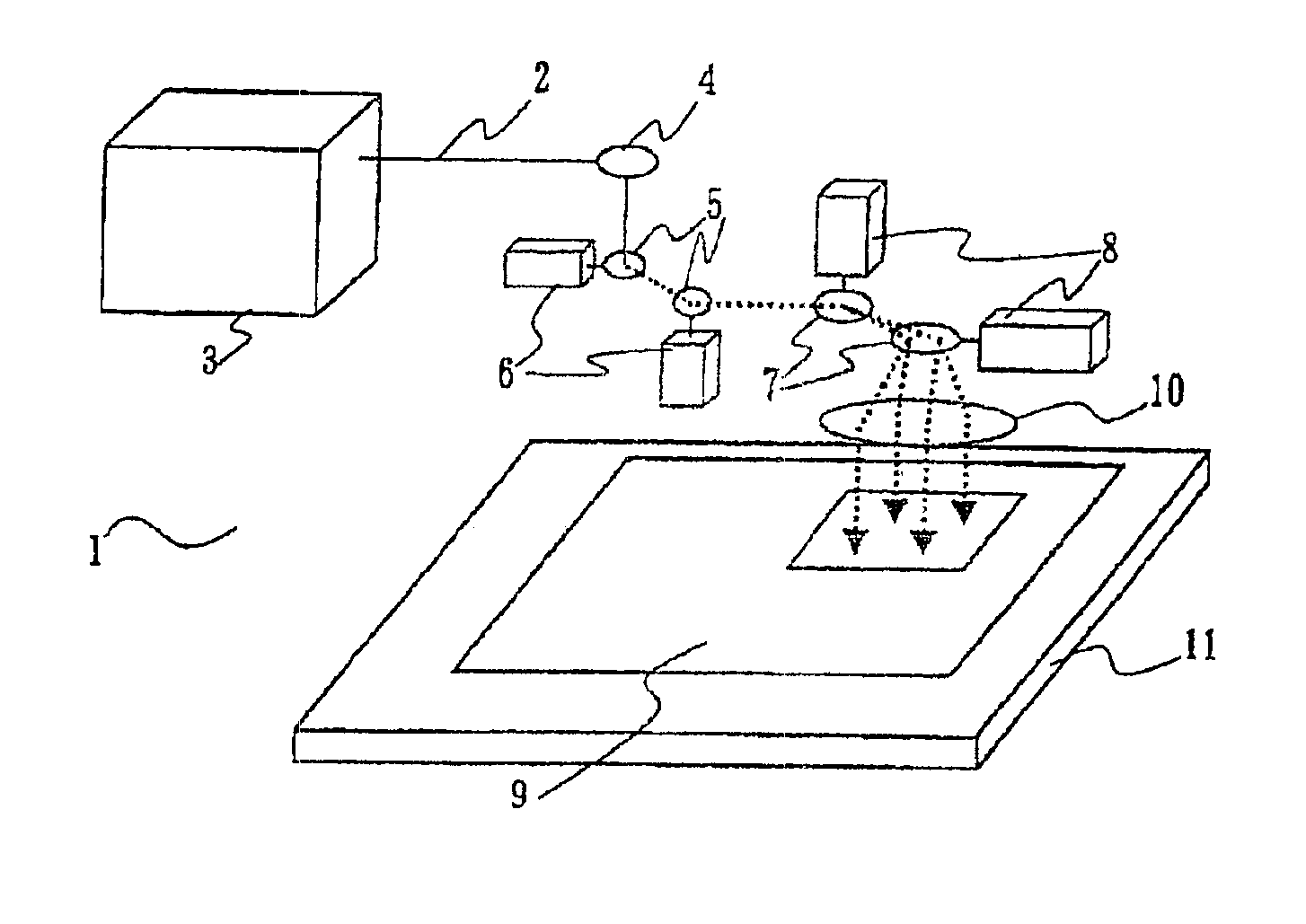
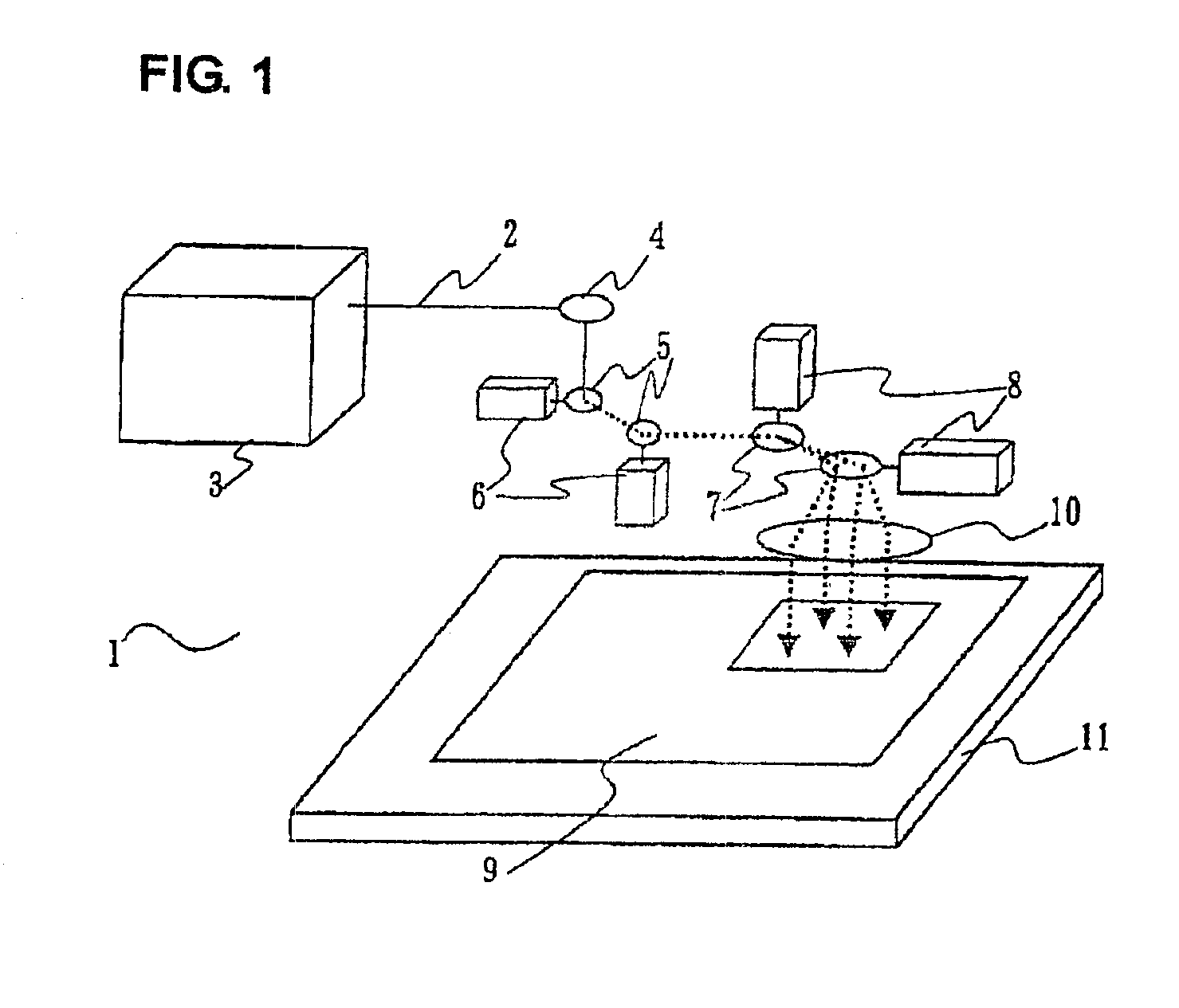
FIG. 1 shows a laser machining device according to the embodiment. In FIG. 1, a laser machining device 1 has: a laser oscillator 3 for generating a laser beam 2; a bend mirror 4 arranged to guide the laser beam 2 emitted from the laser oscillator 3 in a desired direction by reflection; sub-deflecting galvanometer scanners (first galvanometer scanners) 6 having sub-deflecting galvanometer mirrors (first galvanometer mirrors) 5 which are sequentially arranged along an optical path and can be moved to deflect the laser beam 2; galvanometer scanners (second galvanometer scanners) 8 having main deflecting galvanometer mirrors (second galvanometer mirrors) 7 which sequentially arranged along an optical path and can be moved to deflect the laser beam 2; an Fθ lens 10 for converging the laser beam 2 onto an object 9; and an X-Y stage 11 having an upper surface on which the object 9 is fixed and driven on an X-Y plane. The sub-deflecting galvanometer mirrors 5 are constituted by two galvanom...

embodiment 2

FIG. 4 is a schematic diagram of a laser machining device according to Embodiment 2 of the present invention. The same reference numerals as in Embodiment 1 denote components of the same names in the embodiment.

In FIG. 4, a laser machining device 1 has: an aperture 15 for setting the beam spot diameter of a linearly polarized laser beam 18 emitted from a laser oscillator 3 (not shown) to an arbitrary beam spot diameter on an object 9; a splitting means 19 for splitting the laser beam 18 passing through the aperture 15 into a second laser beam (to be referred to as a laser beam 18a hereinafter) and a first laser beam (to be referred to as a laser beam 18b hereinafter); a phase plate 20 for turning a polarization direction of the laser beam 18a at 90°; galvanometer scanners 6 having sub-deflecting galvanometer mirrors 5 which are sequentially arranged along an optical path and can be moved to deflect the laser beam 18b at a small angle; a polarized beam splitter 21 for reflecting the ...

embodiment 3

FIG. 6 is a schematic diagram of a laser machining device according to Embodiment 3 of the present invention. The same reference numerals as in Embodiment 1 denote components of the same names in this embodiment.

In FIG. 6, a laser machining device 1 has: an aperture 15 for setting the beam spot diameter of a laser beam 26 emitted from a laser oscillator 3 (not shown) to an arbitrary beam spot diameter on an object 9; a splitting means 19 for splitting the laser beam 26 passing through the aperture 15 into a laser beam 26a and a laser beam 26b; galvanometer scanners 5b having first sub-deflecting galvanometer mirrors 5a which are sequentially arranged along an optical path and can be moved to deflect the laser beam 26b at a small angle; galvanometer scanners 6b having second sub-deflecting galvanometer mirrors 6a which are arranged along an optical path after the galvanometer scanners 6a and can be moved to deflect the laser beam 26b at a small angle; a main deflecting galvanometer s...


PUM

PropertyMeasurementUnit
wavelengthaaaaaaaaaa
diameteraaaaaaaaaa
lengthaaaaaaaaaa

Abstract

A laser machining device according to the invention is provided with a laser oscillator for generating a laser beam, a main deflecting galvannometer mirror, an Fθ lens, and a sub-deflecting means arranged in an optical path between the laser oscillator and the main deflecting galvanometer mirror. A means for splitting a laser beam is provided, and the sub-deflecting means is inserted into the optical path of one of the split laser beams. At the same time, both the split laser beams are incident from the same main deflecting galvannometer mirror to the Fθ lens, and a numerical aperture in the optical system constituted by the main deflecting galvannometer mirror, the Fθ lens, and an object is set to be not more than 0.08.

Description

TECHNICAL FIELDThe present invention relates to a laser machining device and, more particularly, to a laser machining device used in high-speed precise hole drilling or the like.BACKGROUND ARTFIG. 9 is a general laser machining device for hole drilling. In FIG. 9, a laser machining device 101 has a laser oscillator 103 for generating a laser beam 102, a bend mirror 104 arranged to guide the laser beam 102 emitted from the laser oscillator 103 in a desired direction by reflection, galvanometer scanners 106a and 106b respectively having galvanometer mirrors 105a and 105b serving as movable mirrors sequentially arranged along an optical path, an Fθ lens 108 for converging the laser beam 102 the traveling direction of which is controlled by the galvanometer scanners 106a and 106b onto an object 107, and an X-Y stage 109 driven on an X-Y plane and having an upper surface on which the object 107 is fixed.The operations of the respective components used when hole drilling is performed by u...

Claims


Application Information

Patent Timeline
Patent Type & Authority Patents(United States)
IPC IPC(8): B23K26/067B23K26/00B23K26/38B23K26/06B23K26/08B23K26/064B23K26/082
CPCB23K26/0608B23K26/0643B23K26/0648B23K26/4025B23K26/08B23K26/0807B23K26/381B23K26/067B23K26/082B23K26/382B23K2103/50B23K26/02B23K26/06B23K26/064
Inventor SAKAMOTO, MASAHIKOTAKENO, SHOZUIIWAI, YASUHIKOHOKODATE, TOSHIYUKIKUROSAWA, MIKI
Owner MITSUBISHI ELECTRIC CORP
Why Eureka
Try Eureka