
Heating system

a technology of heating system and heat dissipation device, which is applied in the direction of ohmic-resistance heating, ohmic-resistance heating details, electrical equipment, etc., can solve the problems of complex contributions of these factors, difficult to perform such control, and out of the desired uniformity of temperature distribution, so as to reduce the temperature distribution and reduce the temperature distribution with ease. , the effect of low cos

Inactive Publication Date: 2005-04-05
NGK INSULATORS LTD
View PDF12 Cites 27 Cited by
  • Summary
  • Abstract
  • Description
  • Claims
  • Application Information

AI Technical Summary

Benefits of technology

Even when the heating surface of a ceramic heater has a desired uniformity of temperature before the heater is fixed in a chamber, the temperature distribution may be out of the desired uniformity after the heater is fixed in the chamber, according to the above reasons. It is thus necessary to control or fine tune the supply of electrical power to a resistance heat generator, after a ceramic heater is fixed in a chamber, so as to reduce the temperature distribution on the heating surface.
For example, the second power range is 0 to 20 W provided that the maximum of the auxiliary power source is 20 W and the range of the output indication percentage is 0 to 100 percent. The width of the second power range is 20 W in this case. The second power range for the auxiliary power source is sufficiently smaller than the first power range for the main power source. The temperature control with the auxiliary power source having a smaller power range and the control with the main power source having a wider power range are combined, so that the fine tuning of the temperature distribution may be performed with a high precision.

Problems solved by technology

The contributions of these factors may be complicated and beyond any speculation.
Even when the heating surface of a ceramic heater has a desired uniformity of temperature before the heater is fixed in a chamber, the temperature distribution may be out of the desired uniformity after the heater is fixed in the chamber, according to the above reasons.
It has been, however, difficult to perform such control as follows.
The two-zone control system may not be effective for reducing such cold and hot spots observed in only a small part of the heating surface.

Method used


Image

  • Heating system
  • Heating system
  • Heating system

Examples


example

The experimental results will be described below. The heating system 12 shown in FIG. 6 was produced. The system 12 was fixed in the chamber of a curing system for a coater as shown in FIG. 7.

A ceramic heater was used as the main heating element 3A. The heater is composed of a substrate made of AlN ceramics and a resistance heat generator made of a molybdenum wire. The heating surface 4a of the heater 3A had a diameter of 320 mm. The heater 3A had a thickness of 4 mm. A thermocouple was inserted and embedded within the substrate 4.

The substrates 9 of the auxiliary heating elements 5A to 5D were made of mica. The resistance heat generators 10 were made of nichrome wires. The holding member 13 was formed of stainless steel. The insulating sheet 14 is formed of a polyimide resin. Each auxiliary heating element has an outer diameter of 300 mm, an inner diameter of 220 mm, and a thickness of 1 mm.

The thus obtained heating system 12 was fixed in the chamber 18. Electric power was supplied...


PUM


Abstract

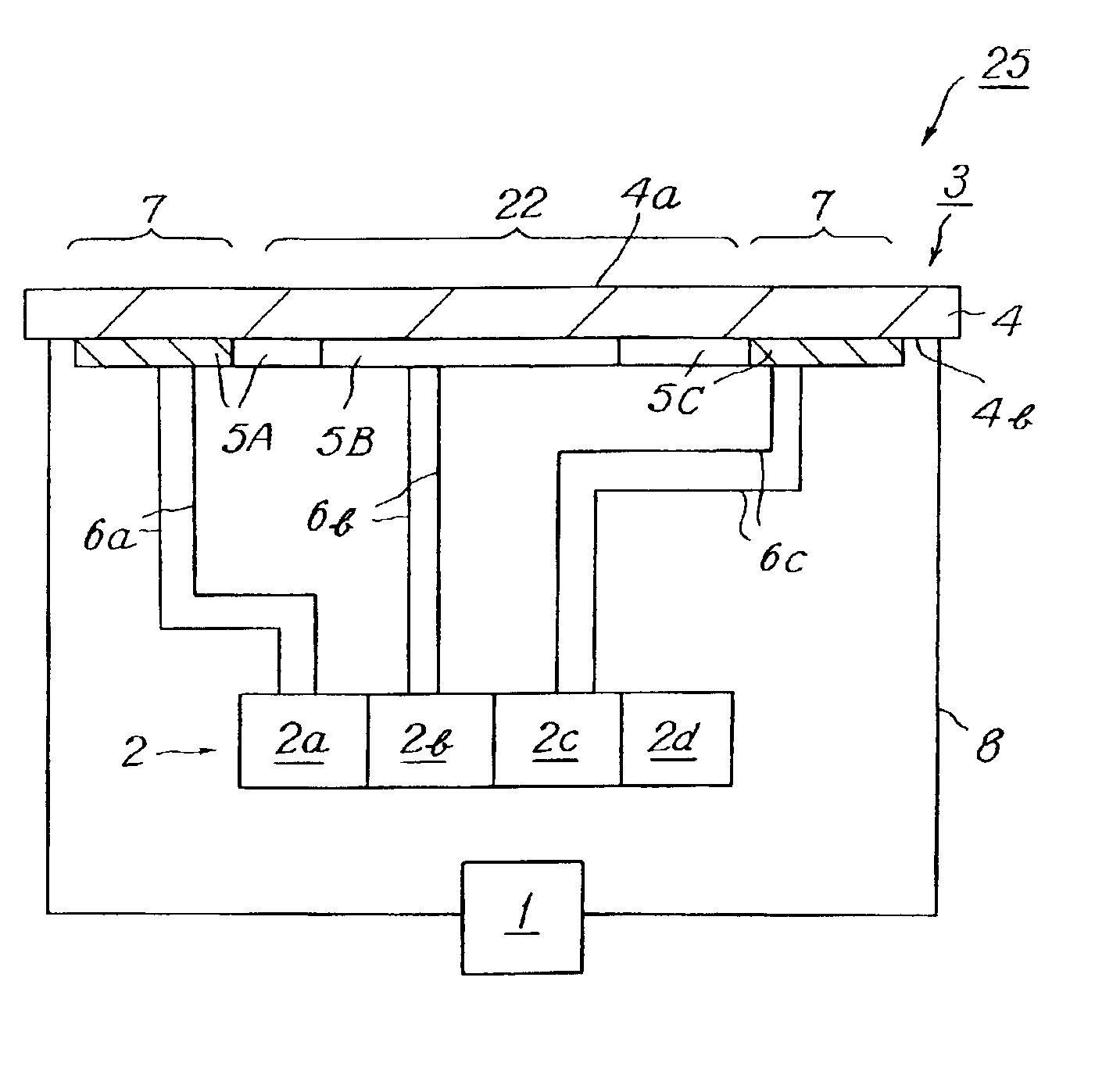
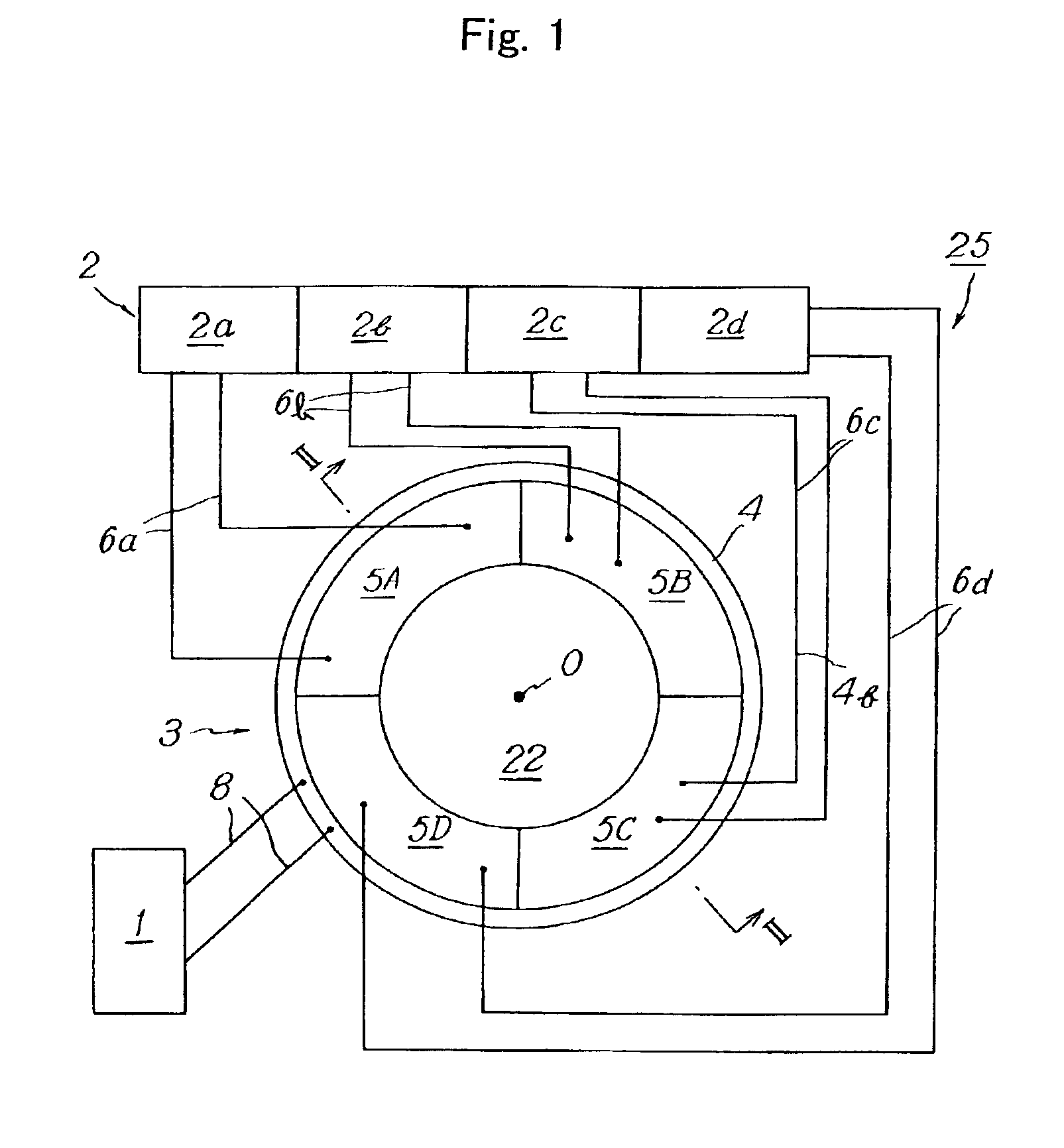
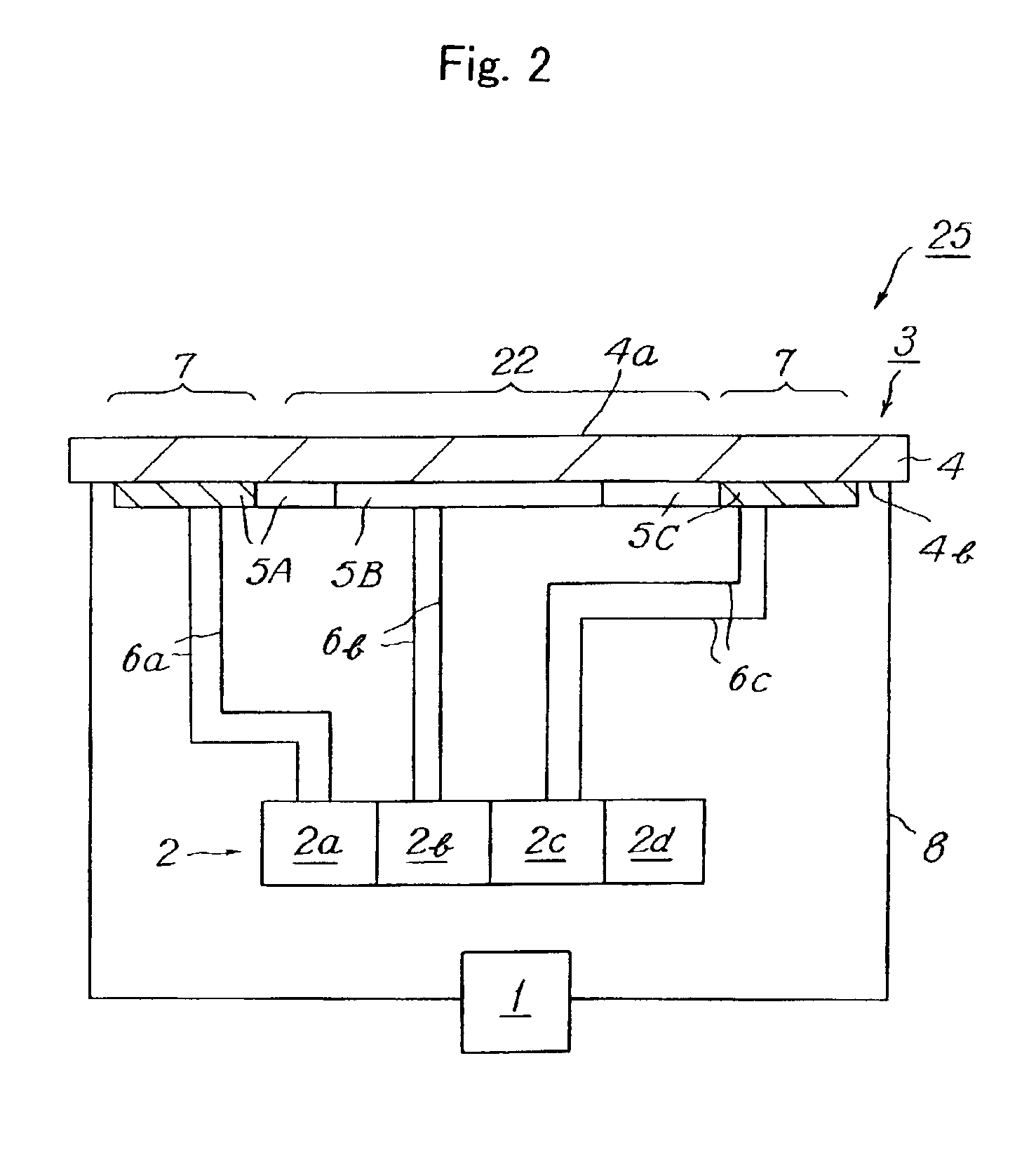
A heating system 25 has a main electric heat-generating element 3 and a heating surface 4a for heating an object, auxiliary electric heat-generating elements 5A to 5D, and a main power source 1 for supplying power to the main heating element. The system 25 further has an auxiliary power source 2 for supplying power to the auxiliary heating elements, and a power source controller for controlling the power supplied to the main heating element and to the auxiliary heating elements respectively and independently. Power supplied to the main heating element 3 is controlled by the controller within a first power range and power supplied to the auxiliary heating elements is controlled by the controller within a second power range. The second power range has a width smaller than that of the first power range so as to control temperature distribution on the heating surface 4a.

Description

This application claims the benefit of Japanese Patent Application P2001-318943, filed on Oct. 17, 2001, the entirety of which is incorporated by reference.BACKGROUND OF THE INVENTION1. Field of the InventionThe invention relates to a heating system.2. Related Art StatementIn a system for producing semiconductors, a ceramic heater may be provided for heating a wafer (substrate) so as to deposit a semiconductor thin film on the wafer from gaseous raw materials such as silane gas by means of thermal CVD or the like. A so called 2 zone heater is known as such ceramic heater. Such 2 zone heater has a ceramic substrate and inner and outer resistance heat generators embedded within the substrate. Separate power supply terminals are connected to the respective heat generators so that electric power may be applied independently on the respective generators. The inner and outer heat generators may be thus independently controlled.Further, in JP-A 5-326112, a resistance heat generator of a ce...

Claims


Application Information

Patent Timeline
Patent Type & Authority Patents(United States)
IPC IPC(8): H01L21/00H05B3/20H01L21/324H05B3/00H05B3/16H05B3/18
CPCH01L21/67103H01L21/324
Inventor YAMAGUCHI, SHINJIGOTO, YOSHINOBUOKAJIMA, HISAKAZUUNNO, YUTAKA
Owner NGK INSULATORS LTD
Learn More