
Magnetic resonance imaging system

a magnetic resonance imaging and magnetic resonance technology, applied in the field of magnetic resonance imaging apparatus, can solve the problem that the operator performing the operation or therapy is not given enough consideration

Inactive Publication Date: 2005-04-05
HITACHI MEDICAL CORP
View PDF4 Cites 32 Cited by
  • Summary
  • Abstract
  • Description
  • Claims
  • Application Information

AI Technical Summary

Benefits of technology

In this apparatus, nuclear magnetic resonance echo signals are repeatedly measured to obtain an image. The reception system has a receiving coil, which is composed of a plurality of overlapped coils, and this receiving coil detects plural series of echo signals. The signal processing system divides the echo signals into plurality regions, performs an image reconstruction operation in parallel using the plural series of echo signals, and combines the images of these plural regions into one image. The sequencer executes an ultra-fast imaging sequence, and, at the same time, reduces the number of phase encoding operations used in the measurement. This sequencer further includes image renewal means for renewing the cross-section corresponding to positional information relevant to a desirable angle and direction.
In this magnetic resonance imaging apparatus, the reception system has a receiving coil, which is composed of a plurality of overlapped coils, and the receiving coil detects plural series of echo signals. The signal processing system divides these echo signals into plural regions, performs an image reconstruction operation in parallel using the plural series of echo signals, and combines images of the plural regions into one image. The sequencer executes an ultra-rapid imaging sequence, and, at the same time, it reduces the number of phase encoding operations used in the measurement. This sequencer further includes image renewal means for renewing the cross-section to be imaged in response to positional information corresponding to a desired angle and direction.

Problems solved by technology

However, sufficient consideration has not been given to the operator performing the operation or therapy while observing the image of a lesion in real time in a magnetic resonance imaging in apparatus having the above-described structure.

Method used


Image

  • Magnetic resonance imaging system
  • Magnetic resonance imaging system
  • Magnetic resonance imaging system

Examples


Embodiment Construction

Hereinafter, an embodiment of the present invention will be described with reference to the drawings.

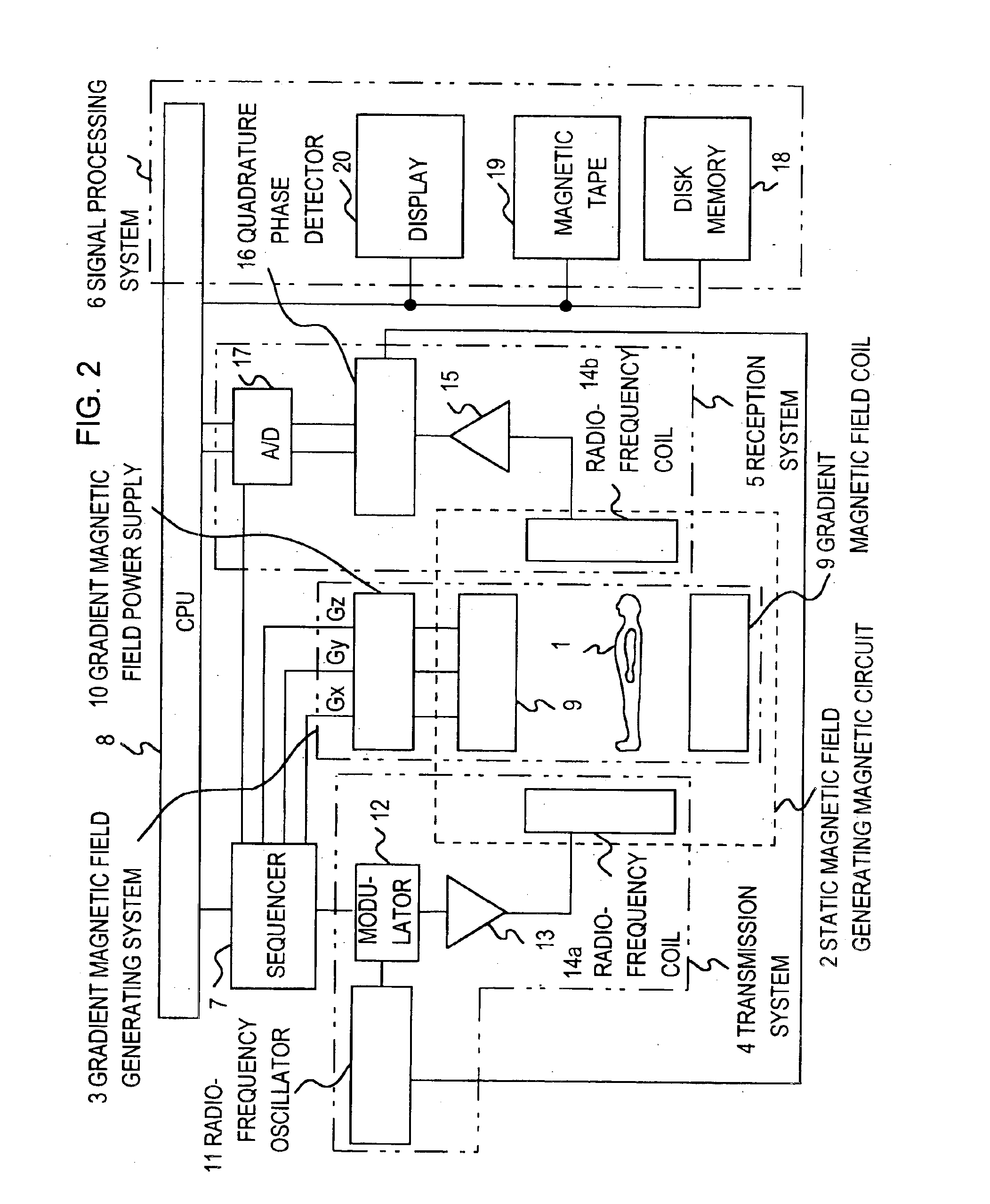
First, the overall structure of a magnetic resonance imaging apparatus to which the present invention is applied, will be described with reference to FIG. 2. This magnetic resonance imaging apparatus is designed to obtain a tomogram of an object to be examined, utilizing the NMR phenomenon. This apparatus is constituted of a static magnetic field generating magnetic circuit 2, a magnetic field gradient generating system 3, a transmission system 4, a reception system 5, a signal processing system 6, a sequencer 7, and a central processing unit (CPU) 8.

In the static magnetic field generating magnetic circuit 2, which is designed to generate a uniform static magnetic field around an object 1 to be examined. magnetic field generating means of the permanent magnet type, resistive magnet type, or superconductive magnet type is placed within a space which is expanded to some extent. This st...


PUM


Abstract

A magnetic resonance imaging apparatus is provided with a sequencer for executing a rapid imaging sequence of up to 100 ms at a full scan, a parallel measurement system for executing a partial encoding measurement in which the number of phase encoding operations performed for the measurement is reduced, an image processing system for reconstructing images from the information obtained though parallel measurements and composing reconstructed images of a plurality of areas to make one image, a display system for displaying the obtained images at a rate of 50 frame / second or more, and an image renewal system for taking in coordinate information of the cross-section to be imaged from position and pointing devices at intervals of about 0.1 second, and renewing the cross-section to be imaged in real time. Thus, imaging on the cross-sections indicated by a device can be performed in real time with high spatial and high time resolution.

Description

FIELD OF THE INVENTIONThe present invention relates to a magnetic resonance imaging apparatus for use in obtaining a tomogram of a desired region of an object to be examined, by utilizing a nuclear magnetic resonance (hereinafter referred to as NMR) phenomenon; and, more particularly the invention relates to a magnetic resonance imaging apparatus for guiding a device that is inserted in the body of the object for performing therapy on the body while observing an image of the body, and to a magnetic resonance imaging apparatus for displaying a moving image representing a time-sequential change of a region of the body with sufficient time resolution so as to monitor the therapeutic effect of the therapy.BACKGROUND OF THE INVENTIONA magnetic resonance imaging apparatus is designed to measure the density distribution, the distribution of the relaxation time and the like of nuclear spins (hereinafter referred to as spins) in a desired region of an object to be examined, utilizing a NMR p...

Claims


Application Information

Patent Timeline
Patent Type & Authority Patents(United States)
IPC IPC(8): A61B5/055G01R33/561G01R33/54G01R33/28
CPCA61B5/055G01R33/5611G01R33/54G01R33/285
Inventor WATANABE, SHIGERUTAKAHASHI, TETSUHIKOTAKESHIMA, HIROTAKASHIMIZU, HIROMICHI
Owner HITACHI MEDICAL CORP
Learn More