Polarized light color filter and video projector comprising the same

a technology of polarized light and filter, which is applied in the direction of polarising elements, picture reproducers using projection devices, instruments, etc., can solve the problems of limiting the reduction of the size of the filter on the whole, the inability to freely vary the ratios of r-light, g-light and b-light during one given period, and the increase in the number of times. , to achieve the effect of increasing the speed, reducing the number of times, and increasing the speed

Inactive Publication Date: 2005-04-05
FUJITSU GENERAL LTD
View PDF16 Cites 5 Cited by
  • Summary
  • Abstract
  • Description
  • Claims
  • Application Information

AI Technical Summary

Benefits of technology

In consequence, therefore, the polarized light color filter according to the present invention does not include the mechanical element as is required in the case of the prior art, and this not only enables the polarized light color filter to be built more compact, provided with higher mechanical strength, have more freedom in varying the ratios of the distribution among the R-light, G-light and B-light during a given period but also enables the switching speed to be increased, thereby contributing to the improvement in utilization rate per light quantity of the light source.
In other words, the contrast of the projected image can be improved by projecting both the modulated light from the reflection optical modulating element provided on one light emission side of the polarized light color filter and the modulated light from the reflection optical modulating element provided on the other light emission side of the polarized light color filter.

Problems solved by technology

(1) A mechanical element is necessary in order to rotate the disk-shaped filter 16, so that the mechanical vibration of the front screen liquid crystal panel 24 caused by the mechanical rotation makes the image on the screen less distinct due to the vibration transmitted to the screen. This tendency increases as the size of the filter becomes smaller. Besides, the dimensions of the filter tend to become larger relatively to the size of the actual light transmission area, thereby limiting the reduction of the size of the filter on the whole.
(2) The ratios of the R-light, G-light and B-light in a period are predetermined according to the ratios in the area of the R-light component, G-light component and B-light component transmission filter 16r, 16g and 16b, so that the ratios of the R-light, G-light and B-light cannot be varied freely during one given period.
(3) Since the switching among the R-light, G-light and B-light is made by mechanically rotating the disk-shaped filter 16, the rotating speed cannot be increased freely beyond the limit of the mechanical rotation.
(4) Since the switching among the R-light, G-light and B-light is made by mechanically rotating the diskshaped filter 16, the ratio of the light transmission area 18 for each of the filters 16r, 16g and 16bcorresponding to the R-light, G-light and B-light cannot be increased freely, thereby forcing the utilization rate per quantity of the light of the white light source 20 to be kept at a low level.

Method used


Image

  • Polarized light color filter and video projector comprising the same
  • Polarized light color filter and video projector comprising the same
  • Polarized light color filter and video projector comprising the same

Examples


Embodiment Construction

The embodiments of the present invention will be described below referring to the drawings.

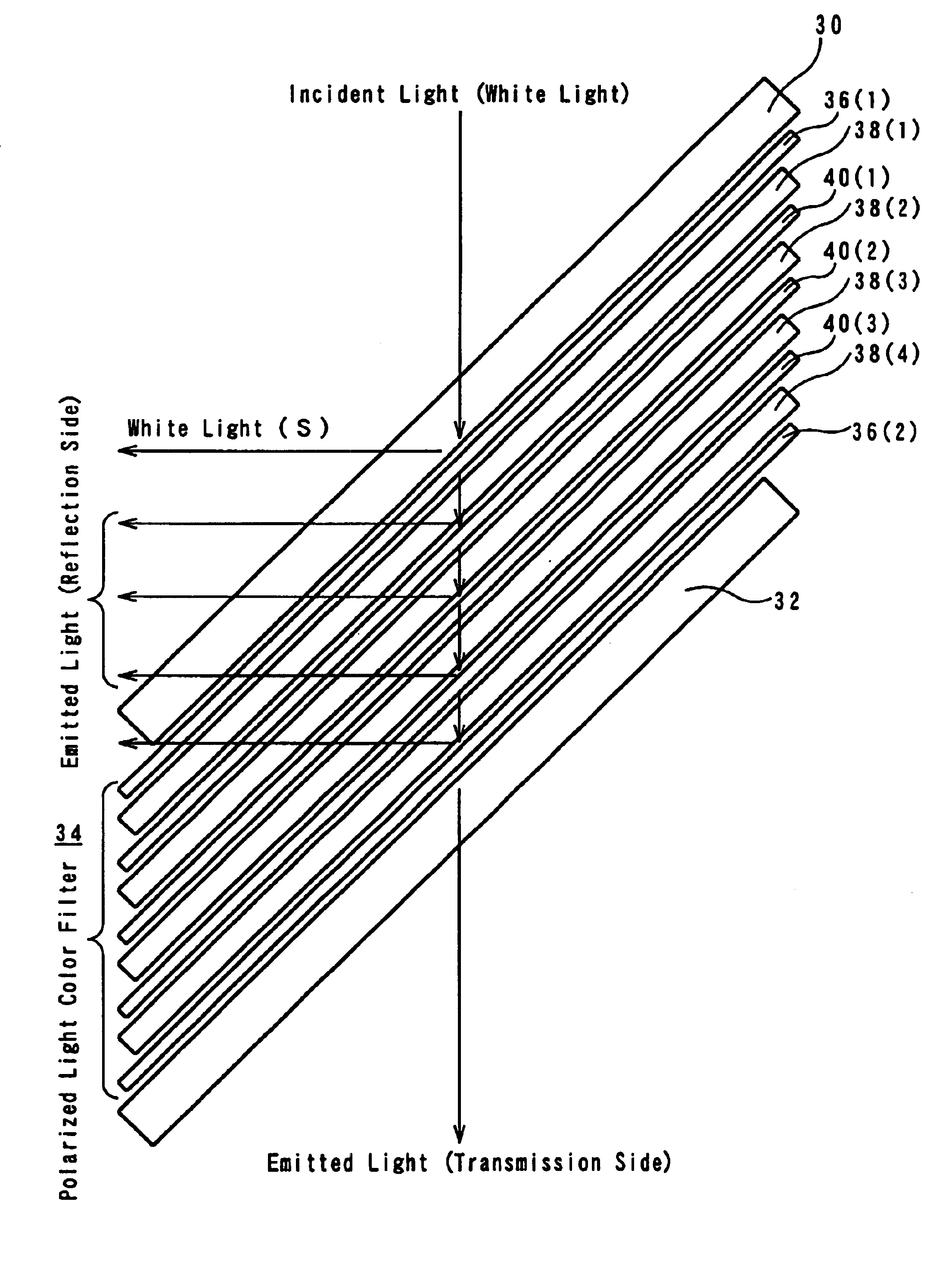
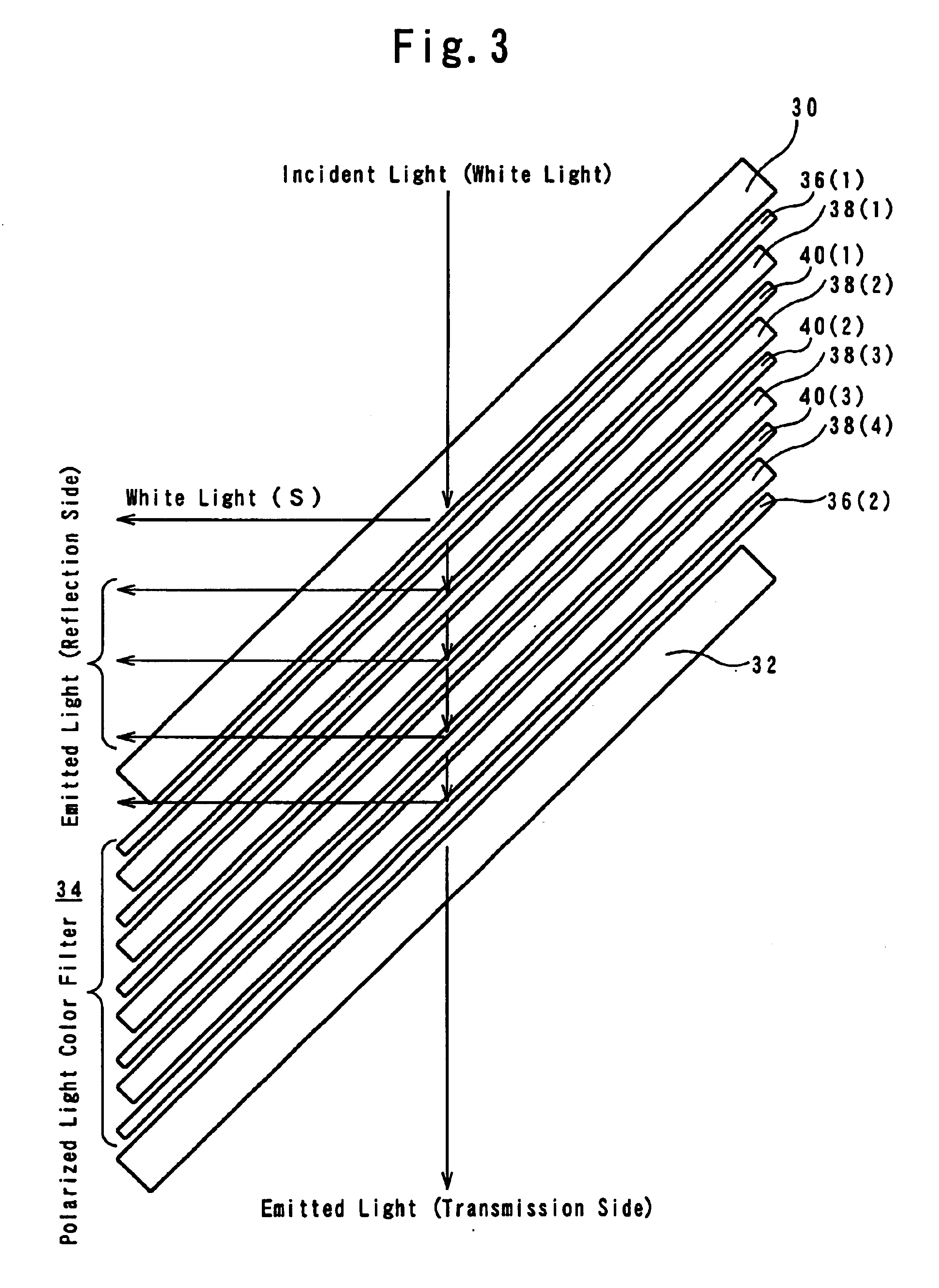
FIG. 3 is a basic exploded construction diagram illustrating an embodiment of the polarized color filter according to the present invention.

In FIG. 3, 30 and 32 represent transparent substrates (e.g., glass substrates) disposed at 45° to the incident light (white light). The polarized light color filter 34 is fixed between the transparent substrates 30 and 32.

Said polarized light color filter 34 comprises a first wide-band polarization spectroscopic element 36(1), a first polarized light converting element 38(1), a first narrow-band polarization spectroscopic element 40(1), a second polarized light converting element 38(2), a second narrow-band polarization spectroscopic element 40(2), a third polarized light converting element 38(3), a third narrow-band polarization spectroscopic element 40(3), a fourth polarized light converting element 38(4) and a second wide-band polarization spectroscopic...


PUM

PropertyMeasurementUnit
polarityaaaaaaaaaa
transparentaaaaaaaaaa
voltagesaaaaaaaaaa

Abstract

A polarized light color filter for producing R, G and B primary lights from inputted white light in time division. The filter is small in size and strong against mechanical vibration. The projections of the R, G and B lights can be arbitrarily varied in one period. The varying speed is high, and the ratio of utilization of the quantity of light from the light source is high. Elements 36(1), 38(1), 40(1), 38(2), 40(2), 38(3), 40(3), 38(4) and 36(2) are in order stacked and bonded between glass substrates (30, 32). The elements 38(1) to 38(4) are polarized light converting elements for selecting either a mode in which the inputted light is outputted as it is by applied voltage control or a mode in which the inputted light is converted from one polarized light to the other and outputted. The elements 40(1) to 40(3) are narrow-band polarization spectroscopic elements reflecting only the S-polarized components of the R, G and B lights and transmitting the other components. The elements 36(1), 36(2) are wide-band polarization spectroscopic elements transmitting the P-polarized components over the full visible range and reflecting the P-polarized components.

Description

TECHNICAL FIELD OF THE INVENTIONThe present invention relates to a polarized light color filter for obtaining the three primary lights (monochromatic light), namely the R (Red) light, G (Green) light and B (Blue) light, from polarized light (P-polarized light or S-polarized light) or mixed light, as the incident light, on the time-division basis, and also relates to a video projector using such a filter.BACKGROUND ARTConventionally, the polarized light color filter 10 is composed as illustrated in FIG. 1, and the video projector 12 incorporating such a polarized light color filter is composed as illustrated in FIG. 2.More particularly, the polarized light color filter 10 is composed of a rotation axis 14 and a disk-shaped filter 16, which is securely fixed to the rotation axis 14, while the disk-shaped filter 16 is composed of three substantially equally portioned filters, namely, 16r, 16g and 16b for respectively transmitting the R-, G- and B-light components. The rotation of the r...

Claims


Application Information

Patent Timeline
Patent Type & Authority Patents(United States)
IPC IPC(8): G02B27/28G02B7/00G03B21/00H04N9/31G02B5/30G02F1/13G02F1/1335
CPCG02B26/008G02B27/283H04N9/3197H04N9/3114H04N9/3167G03B21/00G03B21/006
Inventor TAJIRI, SHINICHIRO
Owner FUJITSU GENERAL LTD
Why Eureka
Try Eureka