Optical sensor for distance measurement

Inactive Publication Date: 2005-04-05
EAGLE RAY CORP
View PDF11 Cites 28 Cited by
  • Summary
  • Abstract
  • Description
  • Claims
  • Application Information

AI Technical Summary

Benefits of technology

Accordingly, in a preferred aspect of the invention, apparatus and method are provided for distance measurement to a remote surface using a laser beam and phase-shift calculations without encountering frequency response, signal to noise ratio, or bandwidth response limitations associated with fast optical detectors. Before detection, reflected radiation from the surface is further modulated to create a radiation signal having a lower frequency than that characteristic of the transmitted and reflected radiation. The lower frequency radiation signal retains the phase-shift information and thus enables implementation of stable, inexpensive low-frequency optical detectors. An optical modulator is employed to modify the received radiation prior to detection so as to create an additional, low frequency component of optical amplitude modulation that preserves the phase-shift associated with the reflected beam. Thus, the resulting phase-shift can be measured with a precision possible within low frequency waveforms and approaching fundamental physical limits of available optical detectors while still retaining the high modulation frequency for the measuring beam which maximizes the achievable accuracy of distance measurement.
Using a laser measuring beam, a first waveform at a high frequency is applied to the transmitted beam directed at the remote surface. Before receiving a reflected beam at a detector, an additional optical modulator is employed to apply a second waveform at a high but different frequency to the reflected beam. The further modulation of the reflected beam creates an additional low frequency component of optical amplitude modulation at the difference between the first and second frequencies. The low frequency component preserves the phase-shift associated with the reflected beam and can be compared with a corresponding reference phase of the measurement beam. In this way, mixing of the information signal down to a convenient low frequency is achieved optically and prior to detection. As a result, limitations on frequency response, limitations on achievable signal to noise ratio, and limitations on response bandwidth associated with optical detectors may be circumvented, enabling measurement of the phase-shift to an accuracy more closely approaching fundamental physical limits. The advantage gained by mixing down to a lower frequency range is that a greater accuracy of phase measurement is possible. The key inventive step of the present invention is the incorporation of means to modulate the electromagnetic or optical signal, rather than an electronic signal, mixing down to a low frequency range prior to detection. The performance-limiting characteristics of such detectors may then be circumvented, resulting in improved overall accuracy of distance measurement when the received reflected beam is of low power.
The above apparatus enables practice of a novel method of determining phase-shift between the first and second electromagnetic radiation signals and the traversed distances to a remote surface comprising the steps of: multiplying the first waveform signal by the second waveform signal modulated at the second frequency for establishing a third waveform signal of known phase and third frequency equal to the difference of the first and second frequencies; modulating the second electromagnetic radiation signal by the second waveform signal to form a third electromagnetic radiation signal; receiving the third electromagnetic radiation signal at the detector for establishing a detector output waveform signal having a shifted phase at the third frequency; and comparing the known phase and the shifted phase for establishing a phase-shift between the first and second electromagnetic radiation signals, the phase-shift being related to the distance to the remote surface. Preferably, high frequency first and second electromagnetic radiation signals are modulated by a second waveform signal having a high second frequency which is substantially equal to the first frequency so that the resulting third frequency is a low frequency which is easily and accurately detected.

Problems solved by technology

However, when measurements are made on an optically rough surface, the received reflected beam is of low power, particularly if the power of the transmitted beam is limited to prevent any significant risk of damage to the eyes of an operator.
Available optical detectors are incapable of measuring low power beams at high frequencies.
Accordingly, under low power conditions, the characteristics of the available optical detectors limit the maximum practical modulation frequency, the maximum achievable signal to noise ratio and, consequently, adversely affect the accuracy of distance measurement that can be achieved.
However, if the optical detector is not capable of resolving the information from the beam, then the output will have a low signal to noise ratio.

Method used


Image

  • Optical sensor for distance measurement
  • Optical sensor for distance measurement
  • Optical sensor for distance measurement

Examples


example 1

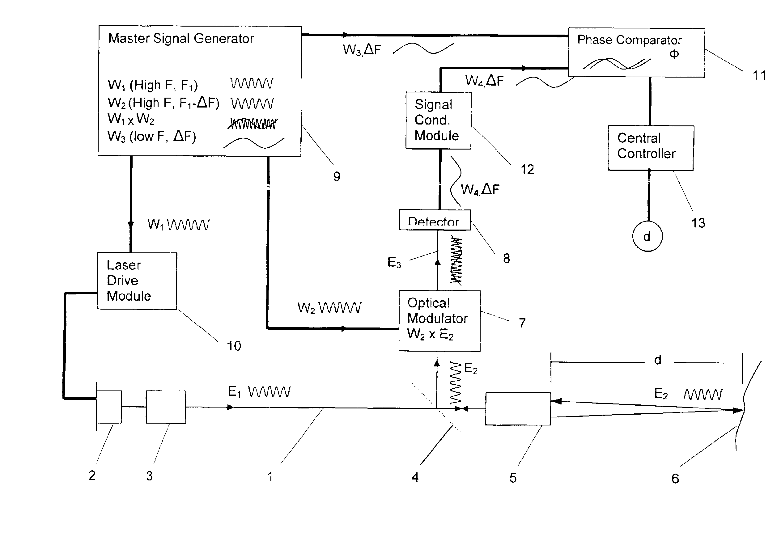
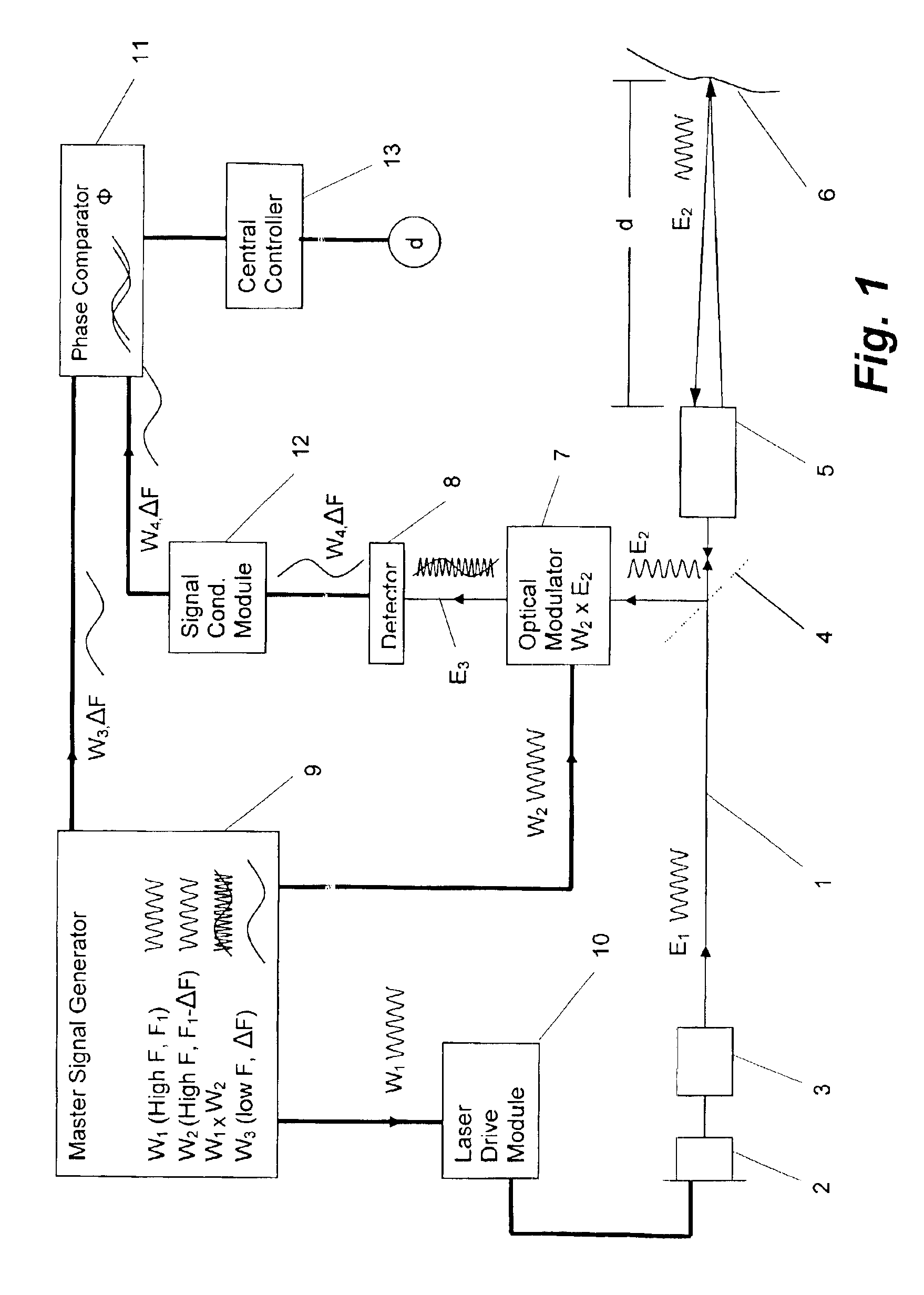
With reference to FIGS. 3-8, a simplified practical theoretical example is provided in which a transmitted beam having waveform E1 at a frequency F1 of 1 GHz, is directed at a remote surface 6. A reflected beam E2, retaining frequency F1, is modulated using a modulating waveform W3, at frequency F2, for creating a mixed electromagnetic radiation signal E3 before being received at the detector 7. The frequency F2 of the modulating beam W3 was chosen to result in a difference frequency ΔF which more practically and graphically illustrates the resulting phase-shift φ. BasicallyE1=Sin(2πF1t)where F1=1 GHz, no DC offset; andE2=Sin(2πF1t−φ)where E2 is phase-shifted E1 due to round trip 2d;φ=4πF1d / c, c=3×10⁸ ms−1; andd=(37.5+n*150)mm yields φ=π / 2 radians

The transmitted and reflected waveforms E1,E2 are shown in FIG. 3.

According to the present invention, the modulating waveform W3 at frequency F2 is applied to the reflected waveform E2. In an actual application applied for high accuracy, a ...

example 2

With reference to FIG. 9, a simple in-line experimental arrangement was used to validate measurement principles of the present invention.

A low power 1 GHz laser beam, emulating that reflected back from a rough object or surface 6 was modulated at a frequency difference of 500 Hz. The distance d of a fiber emitter 30 from a fiber receiver 31 was precisely varied using a linear translation stage. Implementing the present invention to determine distance d, the detector 8 measured phase-shifts φ with a precision of 1.2 degrees per millimeter of movement. The detector 8 achieved this precision without the need to react to frequencies greater than 500 Hz. This precision was achieved because the phase-shift can now be measured while still implementing a 1 GHz output beam having a wavelength of (0.3 meters) of 300 mm. Movement resolution at 1.2 degrees is 1.2 / 360*300 mm=1 mm. In contradistinction, however impractical, an optical detector 8 capable of direct measurement of phase-shift φ from...


PUM


Abstract

Apparatus and method are provided for distance measurement to a remote surface using high frequency modulated transmitted and reflected laser beams and phase-shift calculations. To improve phase-shift resolution, the reflected bean is further modulated, before detection, at a high frequency similar yet different from that of the transmitted beam so as create a resulting detector signal having at least a lower frequency signal which is easily detected by a response limited detector. The lower frequency signal retains the phase-shift information and thus enables determination of the phase-shift information with stable, inexpensive low-frequency optical detectors. Three-dimensional mapping can performed wherein one or more apparatus employ a plurality of detectors or a scanner producing a plurality of sequential reflected beams, each of which results in a plurality of phase-shift information for an area on the surface.

Description

FIELD OF THE INVENTIONThis invention relates to optical devices for the measurement of distance. In particular, the invention is related to devices wherein an amplitude-modulated beam of light is reflected from a remote surface which may be optically rough, and the phase difference between the transmitted beam and the received reflected beam is used to determine the distance to the remote surface.BACKGROUND OF THE INVENTIONExisting implementations of the amplitude-modulated, phase-shift measurement technique are capable of very high accuracy when the remote surface is a cooperative target such as a retro-reflective prism. Under these conditions, the reflected beam is of relatively high power when it is received at the instrument, enabling photoelectric detection of even very high frequency modulation to be achieved with a high signal to noise ratio. Under such ideal conditions, at higher modulation frequencies, the distance over which the phase difference between the transmitted and...

Claims


Application Information

Patent Timeline
IPC IPC(8): G01S17/36G01S17/00G01S7/493G01S7/48G01C3/06G01S7/481G01S7/4915
CPCG01S7/4812G01S7/4915G01S17/36G01S7/493
Inventor BARKER, ANDREW J.
Owner EAGLE RAY CORP
Why Eureka
Try Eureka