Method of operating a combustion plant and a combustion plant

a combustion plant and combustion technology, applied in the direction of machines/engines, lighting and heating apparatus, separation processes, etc., can solve the problems of reducing the efficiency of combustion plants, and reducing the cost of production of oxygen to a sufficient amount, so as to avoid the emission of carbon dioxide to the environment, the effect of efficient heat use and avoiding coke formation

Inactive Publication Date: 2005-04-12
NORSK HYDRO ASA +1
View PDF8 Cites 42 Cited by
  • Summary
  • Abstract
  • Description
  • Claims
  • Application Information

AI Technical Summary

Benefits of technology

Said heated oxygen-depleted gas mixture which is supplied to the first gas turbine has thus been heated without taking part in the actual combustion process. Since this heated oxygen-depleted gas is used to run a gas turbine, the energy in this heated gas is used in an efficient manner and since the gas that runs the first gas turbine has not gone through a combustion, this gas comprises no essential amount of undesired nitrogen oxides or carbon dioxide. The energy in the heated oxygen-depleted gas is thus used in an efficient manner without causing undesired emissions. At the same time of course the energy in said combustion gases is used, since these gases are conducted to another turbine for running the same. With the method according to the invention a high efficiency may thus be obtained at the same time as undesired emissions are avoided.
According to a further advantageous manner of carrying out the method, electric energy is derived from the membrane reactor device. This constitutes an optimal use of the energy that is produced in the membrane reactor device.

Problems solved by technology

It is possible to recover carbon dioxide from a combustion gas, but since the concentration of carbon dioxide usually is low and since the gas contains other substances, such as oxygen and nitrogen, it is relatively complicated, to recover the carbon dioxide.
It is however relatively expensive to produce oxygen to a sufficient amount.

Method used


Image

  • Method of operating a combustion plant and a combustion plant
  • Method of operating a combustion plant and a combustion plant
  • Method of operating a combustion plant and a combustion plant

Examples


Embodiment Construction

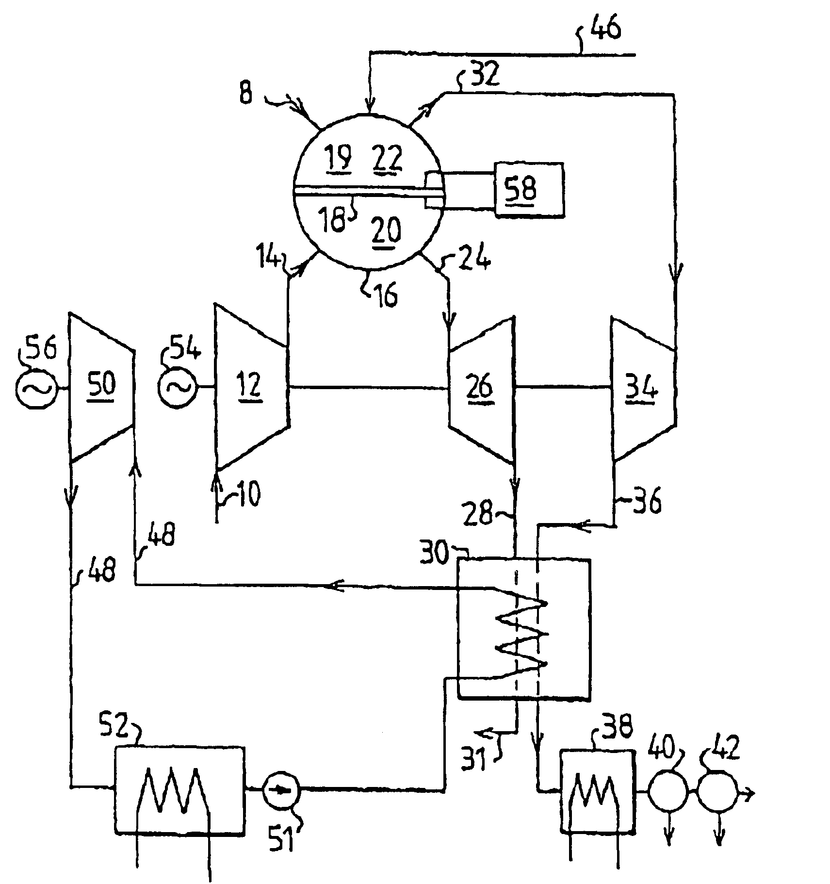
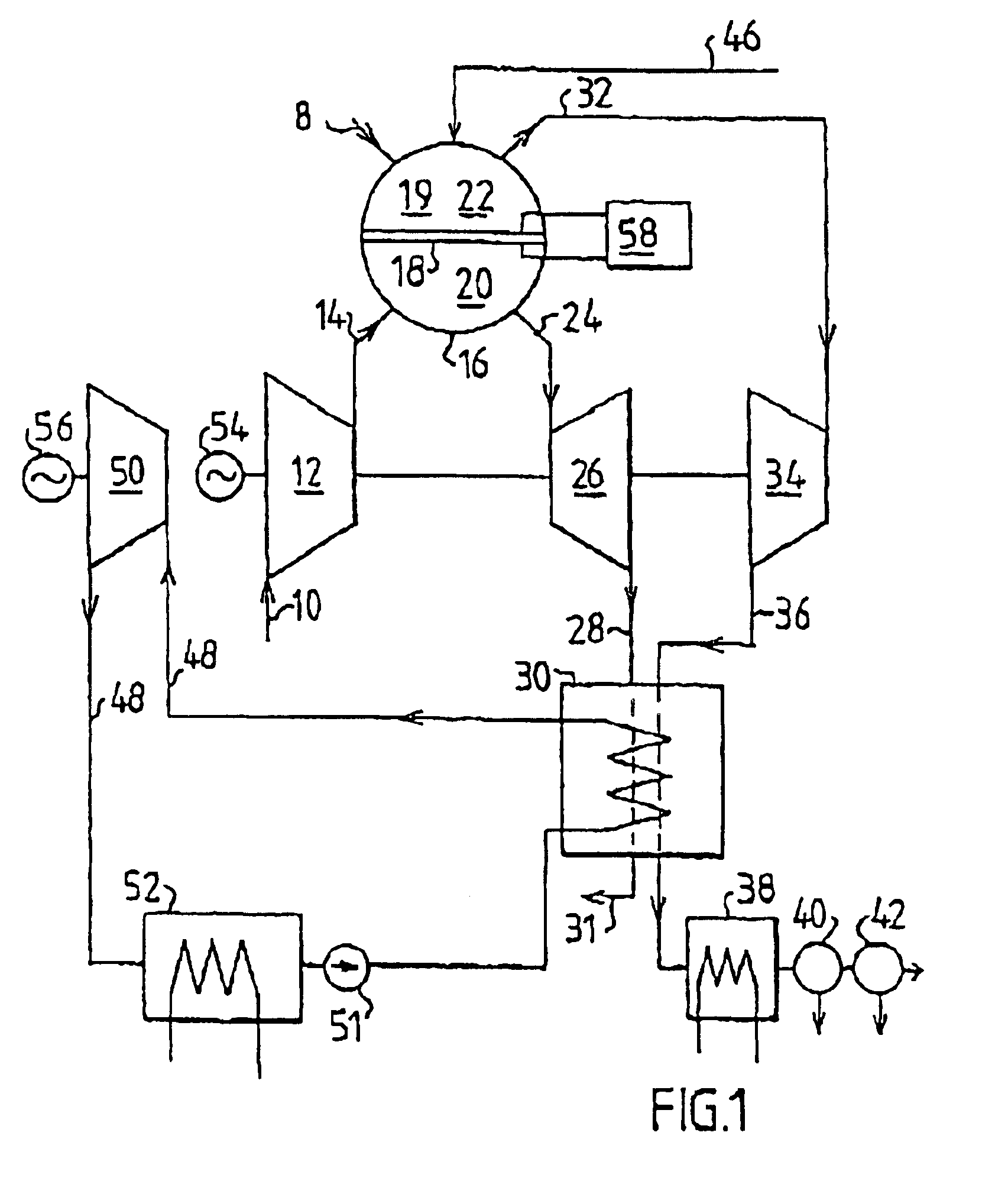
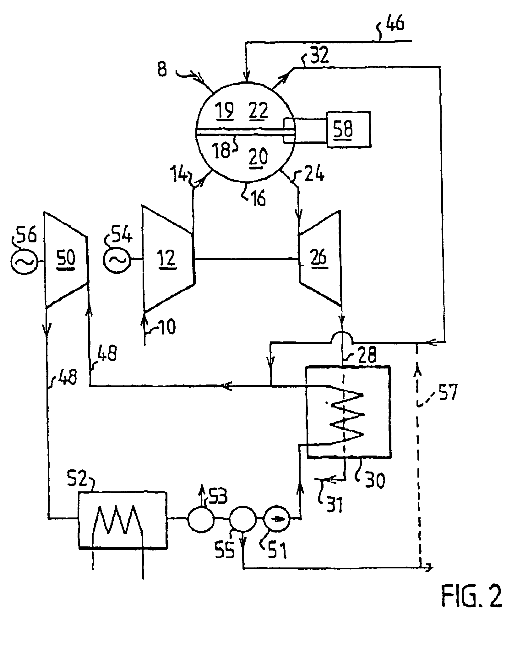
The invention will now first be described with reference to FIG. 1 and FIG. 2. These figures show embodiments of the combustion plant according to the invention. The method according to the invention will be clear from the description of the function of the plants according to these figures.

FIG. 1 shows that a gas mixture, preferably air, is conducted via an inlet 10 to a compressor 12. The compressed gas mixture is further conducted via a first conduit means 14 to a membrane reactor device 16. The membrane reactor device 16 comprises a membrane filter device 18 for separating oxygen from a gas mixture and a combustion space 19 for the combustion of a fuel. This fuel is supplied via a fuel inlet 8. The fuel may for example consist of natural gas or other fossil fuel. As has been pointed out above, it is not necessary that the membrane filter device 18 and the combustion space 19 are arranged within one and the same casing. However, according to a preferred embodiment, the membrane r...


PUM

PropertyMeasurementUnit
temperatureaaaaaaaaaa
electric energyaaaaaaaaaa

Abstract

The invention concerns a method of operating a combustion plant comprising at least a first gas turbine (26), a second turbine (34, 50) and a membrane reactor device (16) which comprises a membrane filter device (18) for separating oxygen from a gas mixture and a combustion space (19). A gas mixture containing oxygen is supplied to the membrane reactor device (16). At least some oxygen is separated from the gas mixture with the help of the membrane filter device (18). The separated oxygen is used at the combustion in the combustion space (19). The oxygen-depleted gas that is obtained after the separation of oxygen and which has not gone through a combustion process is used to run the first gas turbine (26). Combustion gases run the second turbine (34, 50). The invention also concerns a combustion plant for carrying out the method.

Description

FIELD OF THE INVENTIONThe present invention concerns a method of operating a plant comprising at least a first gas turbine, a second turbine and a membrane reactor device which comprises a membrane filter device for separating oxygen from a gas mixture and a combustion space for the combustion of a fuel. The invention also concerns a combustion plant.There are different requirements and desires of reducing unwanted emissions from combustion plants. It is thus, inter alia, desirable to reduce the emission of nitrogen oxides as much as possible. There is also a desire to reduce the emission of carbon dioxide which is produced at the combustion. It is possible to recover carbon dioxide from a combustion gas, but since the concentration of carbon dioxide usually is low and since the gas contains other substances, such as oxygen and nitrogen, it is relatively complicated, to recover the carbon dioxide.A possibility to simplify the manner of recovering carbon dioxide is that the combustio...

Claims


Application Information

Patent Timeline
Patent Type & Authority Patents(United States)
IPC IPC(8): B01D53/22C01B13/02F02C3/20F02C6/00F01K23/10F02C6/18F23L7/00
CPCB01D53/229C01B13/0251F02C6/00F02C3/20C01B2210/0046
Inventor LINDER, ULFERIKSEN, ERIK HANSANG.SEN, KNUT INGVAR
Owner NORSK HYDRO ASA
Why Eureka
Try Eureka