
Vehicle ignition system using ignition module with reduced heat generation

a technology of ignition module and ignition system, which is applied in the direction of ignition control, other installations, machines/engines, etc., can solve the problems of not being able to operate, many now failing, and excessive heat generation, and achieve the effect of reducing hea

Inactive Publication Date: 2005-04-12
WETHERILL ASSOCS INC
View PDF21 Cites 10 Cited by
  • Summary
  • Abstract
  • Description
  • Claims
  • Application Information

AI Technical Summary

Benefits of technology

"The patent describes an ignition system for vehicles that includes a distributor and a reluctor assembly or pick-up. The system includes an electronic control module that generates a control signal to an ignition coil and switches it on and off. A microprocessor is used to reduce the duty cycle of the control signal when the temperature of the ignition module exceeds a certain threshold. This helps to reduce heat and protect the ignition module from damage. The system can also include a Hall Effect pick-up for detecting crankshaft position and engine RPM, and a temperature sensing circuit for adjusting the control signal based on temperature changes. Overall, the system improves the efficiency and reliability of the ignition system in vehicles."

Problems solved by technology

Millions of earlier designed electronic ignition systems (EIS), however, are still used on earlier vehicle models and are still operable, although many are now failing.
A major drawback of these prior art thick film integrated (TFI) modules and similar ignition modules is the excessive production of generated heat resulting from the large duty cycle and constant ON operation when the TFI module generates signals to the ignition coil to fire the spark at proper timing intervals.
Although the TFI module usually includes a heat sink to aid in absorbing excessive amounts of generated heat at low idle speeds and other automotive operations conditions, excessive heat is still generated, at the TFI module and ignition coil, possibly resulting in logic errors, signal transmission errors, and other automotive problems.

Method used


Image

  • Vehicle ignition system using ignition module with reduced heat generation
  • Vehicle ignition system using ignition module with reduced heat generation
  • Vehicle ignition system using ignition module with reduced heat generation

Examples


Embodiment Construction

The present invention will now be described more fully hereinafter with reference to the accompanying drawings, in which preferred embodiments of the invention are shown. This invention may, however, be embodied in many different forms and should not be construed as limited to the embodiments set forth herein. Rather, these embodiments are provided so that this disclosure will be thorough and complete, and will fully convey the scope of the invention to those skilled in the art. Like numbers refer to like elements throughout.

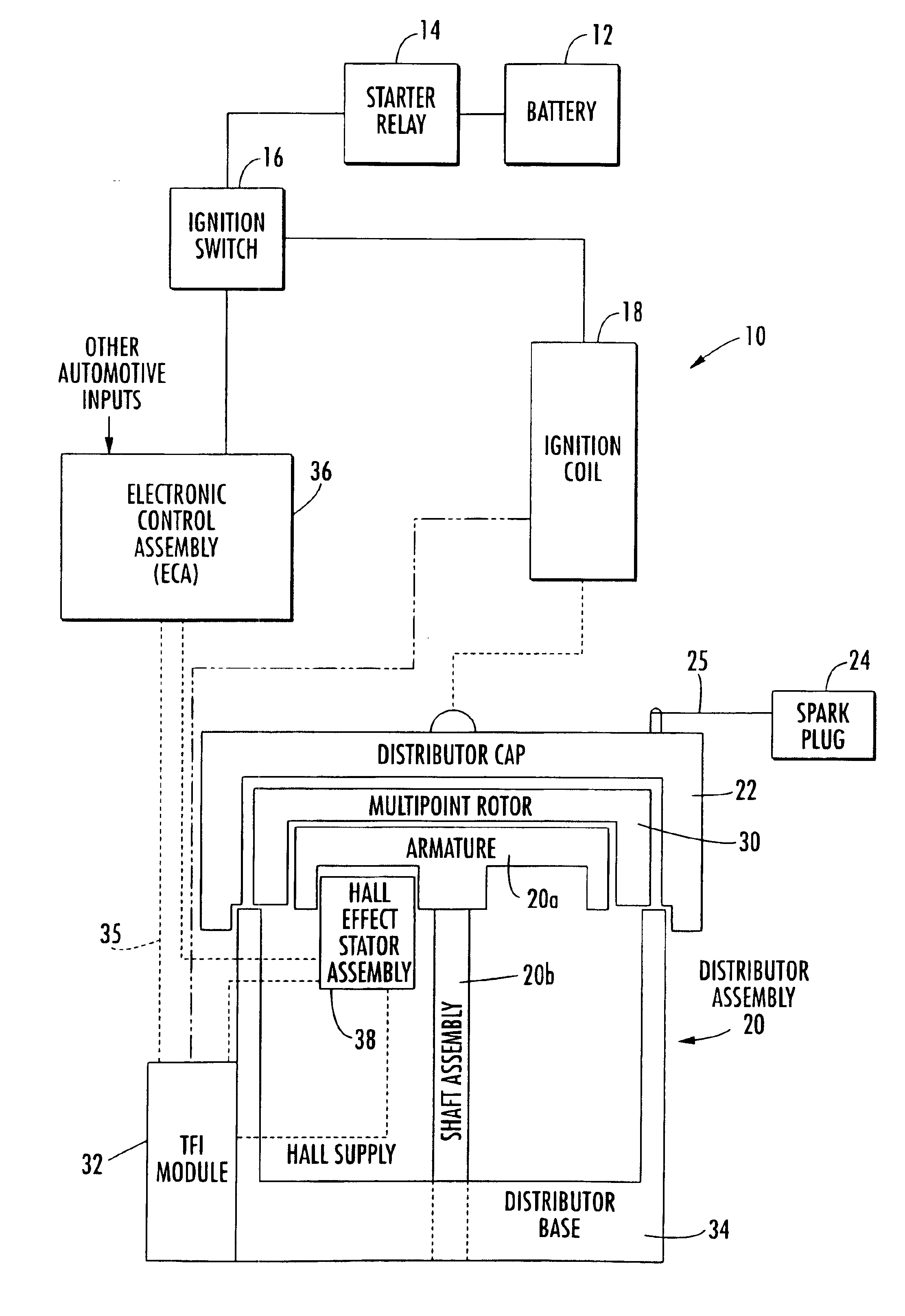
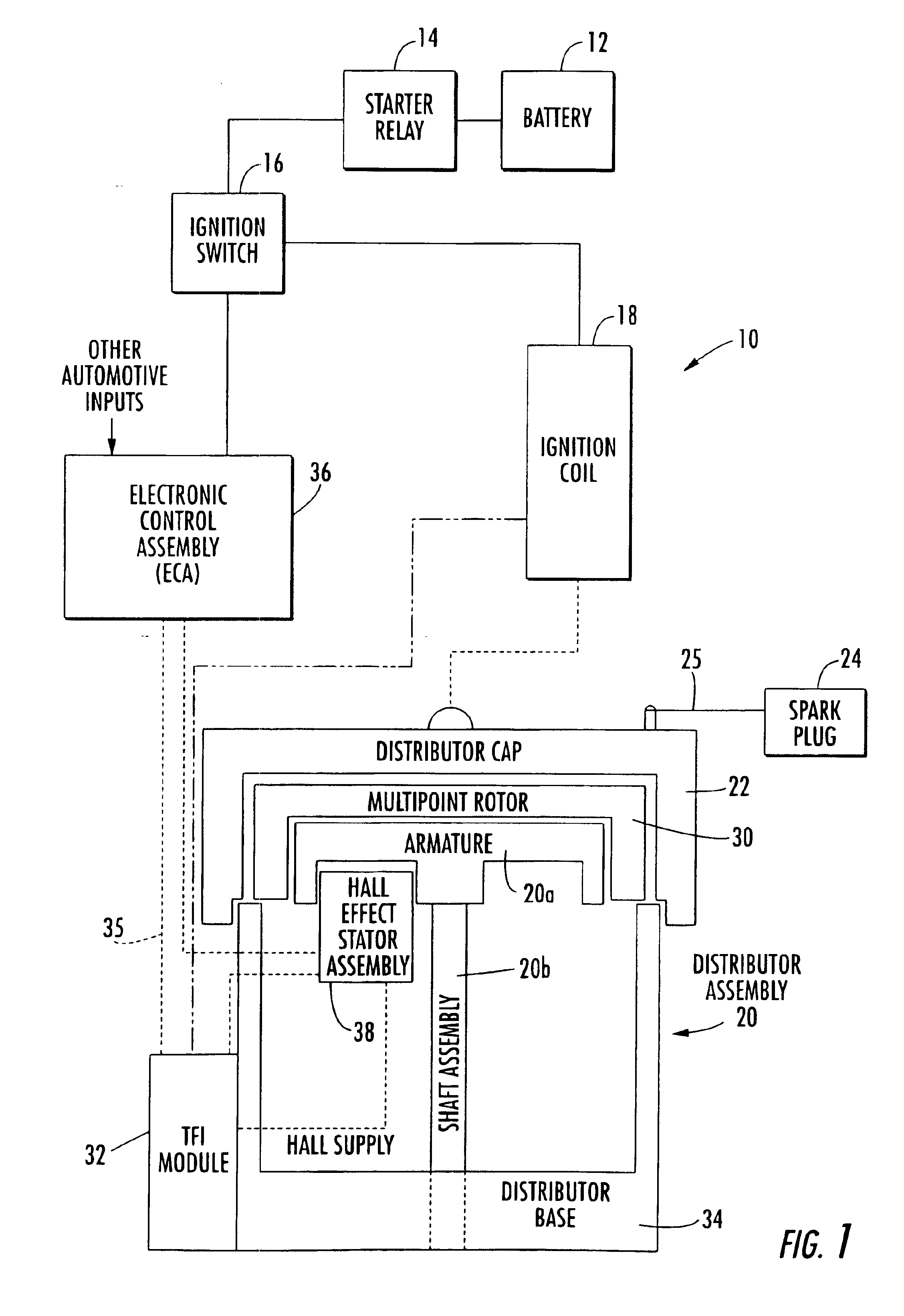
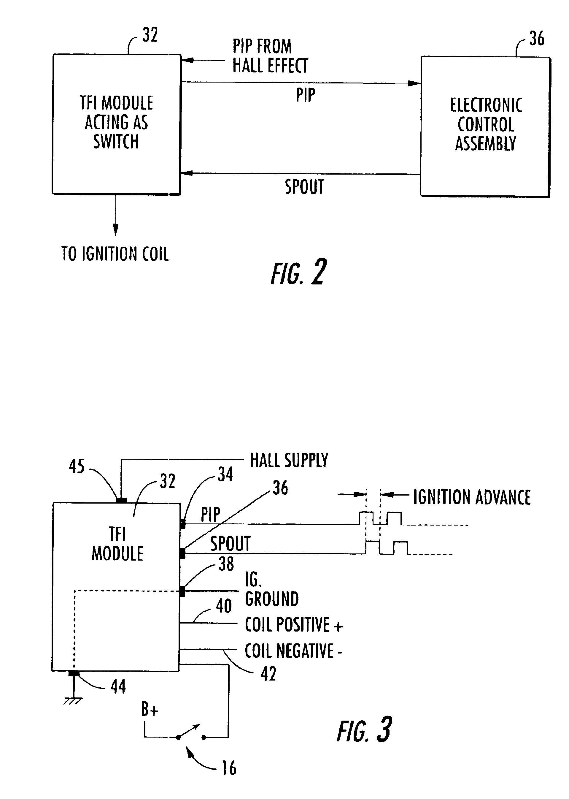
The present invention advantageously provides an ignition system and TFI module and a distributor that uses a reluctor assembly. The ignition coil has primary and secondary windings for generating high voltage signals to spark plugs. An electronic control module (ECM) generates a signal. A distributor has a rotatable reluctor assembly that generates a signal. An ignition module receives a signal from the electronic control module (ECM) and the reluctor assembly....


PUM


Abstract

An ignition system includes an ignition coil, electronic control module that generates a signal, a distributor having a reluctor assembly, and an ignition module for receiving a signal from the electronic control module (ECM) and reluctor assembly. The ignition module includes a microprocessor for generating a control signal to the ignition coil and switching ON and OFF the primary current therein and reducing the duty cycle as applied to the control signal from the ignition module to the ignition coil.

Description

FIELD OF THE INVENTIONThis invention relates to the field of ignition systems for vehicles, and more particularly, this invention relates to ignition systems for vehicles using an electronic control module (ECM), a distributor with a reluctor assembly, and an ignition module that switches ON and OFF the primary current to the ignition coil.BACKGROUND OF THE INVENTIONElectrical ignition systems are used in most automotive vehicles to create a high-voltage current (about 20,000 to about 40,000 volts or more) to a sparkplug and create an arc across the gap at the base of the sparkplug. This high-voltage current creates a strong spark that ignites the air / fuel mixture for combustion. The ignition system also controls the spark timing such that the spark occurs at the right time and in the correct cylinder. Although many different automotive ignition systems have developed over the last century, most ignition systems only differ in the method or system used to create the spark.In the ori...

Claims


Application Information

Patent Timeline
Patent Type & Authority Patents(United States)
IPC IPC(8): F02P7/03F02P7/07F02P7/00
CPCF02P7/07F02P7/035
Inventor MORRISSETTE, GARY E.BROWNING, REGINALD L.
Owner WETHERILL ASSOCS INC
Learn More