
Methods of making fluoride crystal and fluoride crystal lens

a technology of fluoride crystal and fluoride crystal, which is applied in the direction of polycrystalline material growth, after-treatment details, and under a protective fluid, etc., can solve the problems of characteristic deterioration, large volume drop of raw material, and deterioration of optical characteristics during repeated irradiation

Inactive Publication Date: 2005-04-12
CANON KK
View PDF8 Cites 10 Cited by
  • Summary
  • Abstract
  • Description
  • Claims
  • Application Information

AI Technical Summary

Benefits of technology

It is an object of the present invention to provide a method of making a fluoride crystal in which the light transparency does not deteriorate by consecutive irradiation of high output shortwave light over long time periods.
It is a further object of the present invention to provide a method of making a fluoride crystal which can produce a highly reliable optical article.
It is a still further object of the present invention to provide a method of making a fluoride crystal which does not need a crushing step and can produce optical articles with low production costs.

Problems solved by technology

When high purity powdery raw material prepared by a synthetic process is melted using these methods, the volume of the raw material vastly decreases during melting in a crystal growing furnace due to the low bulk density of the powder.
Although the fluoride crystal obtained by the method set forth above exhibits more satisfactory characteristics in general visible light optical articles than those obtained by other prior art methods, its optical characteristics deteriorate during repeated irradiation cycles of high output light having a short wavelength, such as an excimer laser beam.
It was found that large amounts of impurities, e.g. water, iron, nickel and chromium, are included in the fluoride raw material of step S3 set forth above, and these impurities cause characteristic deterioration during consecutive irradiation of high-output short-wavelength light over long time periods.
Thus, this method inefficiently produces fluoride crystal and has high production costs.
If large crystal production is sought using this method, a larger furnace must be provided, resulting in an increase in start-up costs.

Method used


Image

  • Methods of making fluoride crystal and fluoride crystal lens
  • Methods of making fluoride crystal and fluoride crystal lens
  • Methods of making fluoride crystal and fluoride crystal lens

Examples


first embodiment

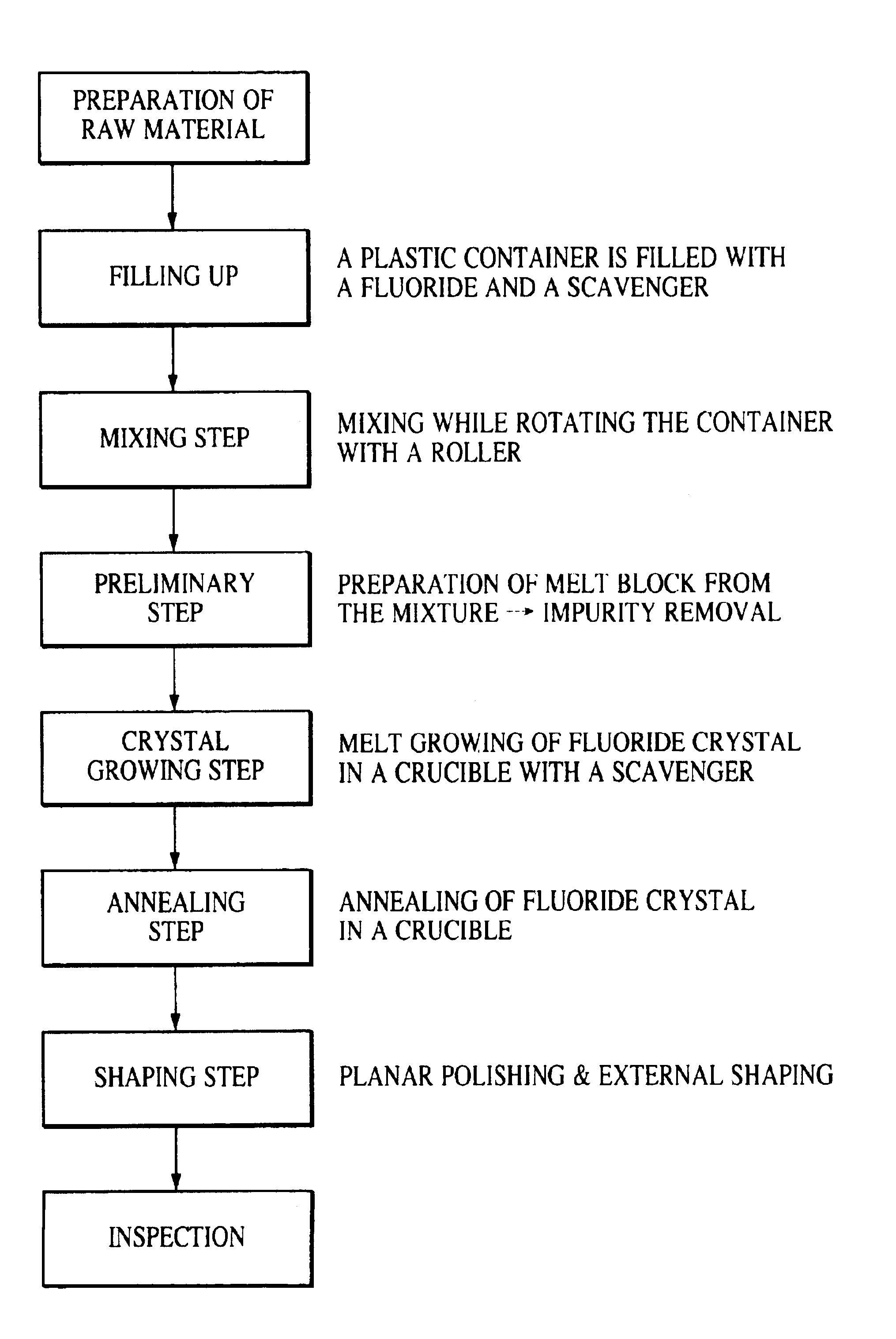
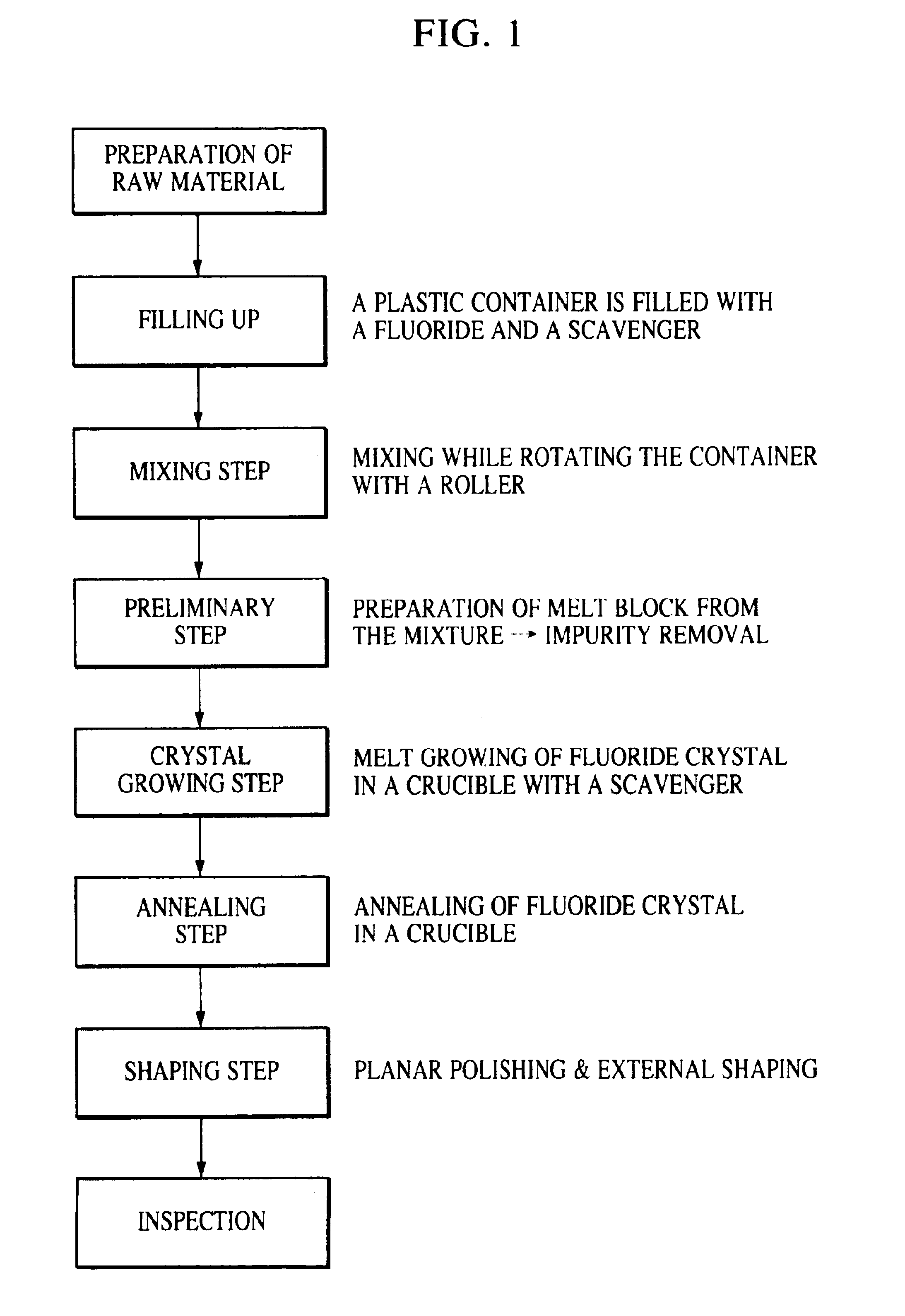
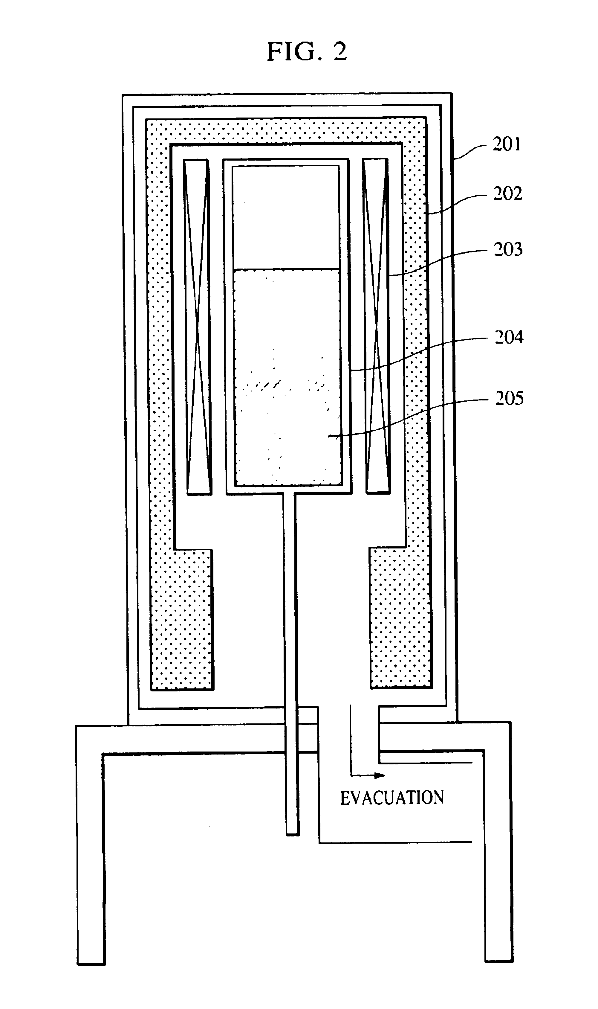
A first embodiment of the present invention will now be illustrated with reference to FIGS. 1 thorough 4. FIG. 1 is a flow chart for illustrating fluoride crystal production steps in accordance with the first embodiment of the present invention, and FIG. 2 is a cross-sectional view of a refining furnace used in the preliminary step shown in FIG. 1. The refining furnace comprises a chamber 201, a thermal insulation material 202, a heater 203 and a first crucible 204 to melt fluoride 205.

FIG. 3 is a cross-sectional view of a block-type crystal growing furnace used in the crystal growing step shown in FIG. 1. The block-type crystal growing furnace comprises a chamber 301, a thermal insulation material 302, a heater 303, a block-type second crucible 304 for melting and crystallizing fluoride 305, and a crucible lowering mechanism 306. FIG. 4 is an annealing furnace used in the annealing step shown in FIG. 1. The annealing furnace comprises a chamber 401, a thermal insulation material 40...

second embodiment

FIG. 5 is a flow chart illustrating a fluoride crystal production process in accordance with a second embodiment of the present invention. In the second embodiment, the preparation of raw material and mixing steps are identical to the first embodiment, but a pressing step is provided instead of the preliminary step in the first embodiment. Thus, the crystal growing step in the second embodiment is different from that in the first embodiment. Regarding the annealing step, both embodiments can be the same. The pressing and annealing steps in the second embodiment will be illustrated.

(Pressing Step)

FIG. 6 is a cross-sectional view which illustrates pressing fluoride powder with a powder pressing machine. A fluoride mixture 604 is placed in a mold 602 and press-formed with a pressing member 603 to increase the bulk density. A preferable pressing force is 500 kgf / cm2.

(Growing Step)

The fluoride block prepared in the pressing step is transferred to the second crucible 304 set forth above, ...

third embodiment

FIG. 7 is a cross-sectional view of a crystal growing furnace which is used for making a fluoride crystal in a third embodiment in accordance with the present invention. This crystal growing furnace produces a disk-shaped fluoride crystal having a relatively large thickness and is called a disk-type furnace. The disk-type crystal growing furnace comprises a chamber 701, a thermal insulation material 702, a heater 703, partitions 707, a disk-type cylindrical crucible 708 for melting and crystallizing fluoride 705 and a crucible lowering mechanism 706. The crucible 708 is divided into a plurality of sections by the partitions 707 and the divided sections connect to each other through small openings 704 provided in the centers of the partitions 707. The same steps as in the first embodiment or as in the second embodiment are also applicable to the third embodiment except for the use of the disk-type crystal growing furnace. It is preferred that each section of the crucible 708 has a di...


PUM

PropertyMeasurementUnit
temperatureaaaaaaaaaa
wavelengthsaaaaaaaaaa

Abstract

A method of making a fluoride crystal suitable for use as an optical element is disclosed. The method includes a mixing step for mixing a prepared raw fluoride material with a scavenger to yield a fluoride mixture. In a preliminary step, the fluoride mixture is formed into a fluoride disk. A grown fluoride crystal is formed by melting and then gradually cooling the fluoride disk in a cylindrical crucible. The grown fluoride crystal is then annealed.

Description

BACKGROUND OF THE INVENTION1. Field of the InventionThe present invention relates to methods of making fluoride crystals and fluoride crystal lenses. In particular, the present invention relates to a method of making a fluoride crystal which is used in optical articles such as lenses which are transparent to excimer laser beams and the like.2. Description of the Related ArtExcimer lasers have attracted attention as the only high-output laser which can oscillate in an ultraviolet region, and have been applied in electronic, chemical and energy industrial fields. In these industrial fields, the excimer laser is used for processing metal, resin, glass, ceramic and semiconductor articles as well as for chemical reactions.The equipment for generating an excimer laser beam is known as an excimer laser oscillator. A laser gas such as Ar, Kr, Xe, F2, or Cl2 is filled into a chamber and is excited by electron beam irradiation or electrical discharge. The excited atoms bond to atoms in a grou...

Claims


Application Information

Patent Timeline
Patent Type & Authority Patents(United States)
IPC IPC(8): C30B33/00C30B11/00
CPCC30B11/00C30B33/00C30B29/12
Inventor OBA, TOMORUICHIZAKI, TOSHIO
Owner CANON KK
Learn More