Method for focus detection for optically detecting deviation of the image plane of a projection lens from the upper surface of a substrate, and an imaging system with a focus-detection system

a technology of imaging system and image plane, which is applied in the field of focus detection for optically detecting deviation of the image plane of a projection lens from the upper surface of a substrate, can solve the problems of not much space remaining available, and the working distance of focus detection systems is also relatively large, and achieves short working distances and high image-side numerical apertures.

Inactive Publication Date: 2005-04-12
CARL ZEISS SMT GMBH
View PDF8 Cites 160 Cited by
  • Summary
  • Abstract
  • Description
  • Claims
  • Application Information

AI Technical Summary

Benefits of technology

It is one object of the invention to provide a method for optically detecting deviations of the upper surface of a substrate to be arranged in the vicinity of the image plane of an optical imaging system and the image plane of the optical imaging system and an assoc

Problems solved by technology

However, the problem that, in the case of imaging systems with high numerical apertures and correspondingly short working distances between their exit surfaces of their lenses and the substrate's upper surface, not much space remains available, so that a focusing beam cannot be direct

Method used


Image

  • Method for focus detection for optically detecting deviation of the image plane of a projection lens from the upper surface of a substrate, and an imaging system with a focus-detection system
  • Method for focus detection for optically detecting deviation of the image plane of a projection lens from the upper surface of a substrate, and an imaging system with a focus-detection system
  • Method for focus detection for optically detecting deviation of the image plane of a projection lens from the upper surface of a substrate, and an imaging system with a focus-detection system

Examples


second embodiment

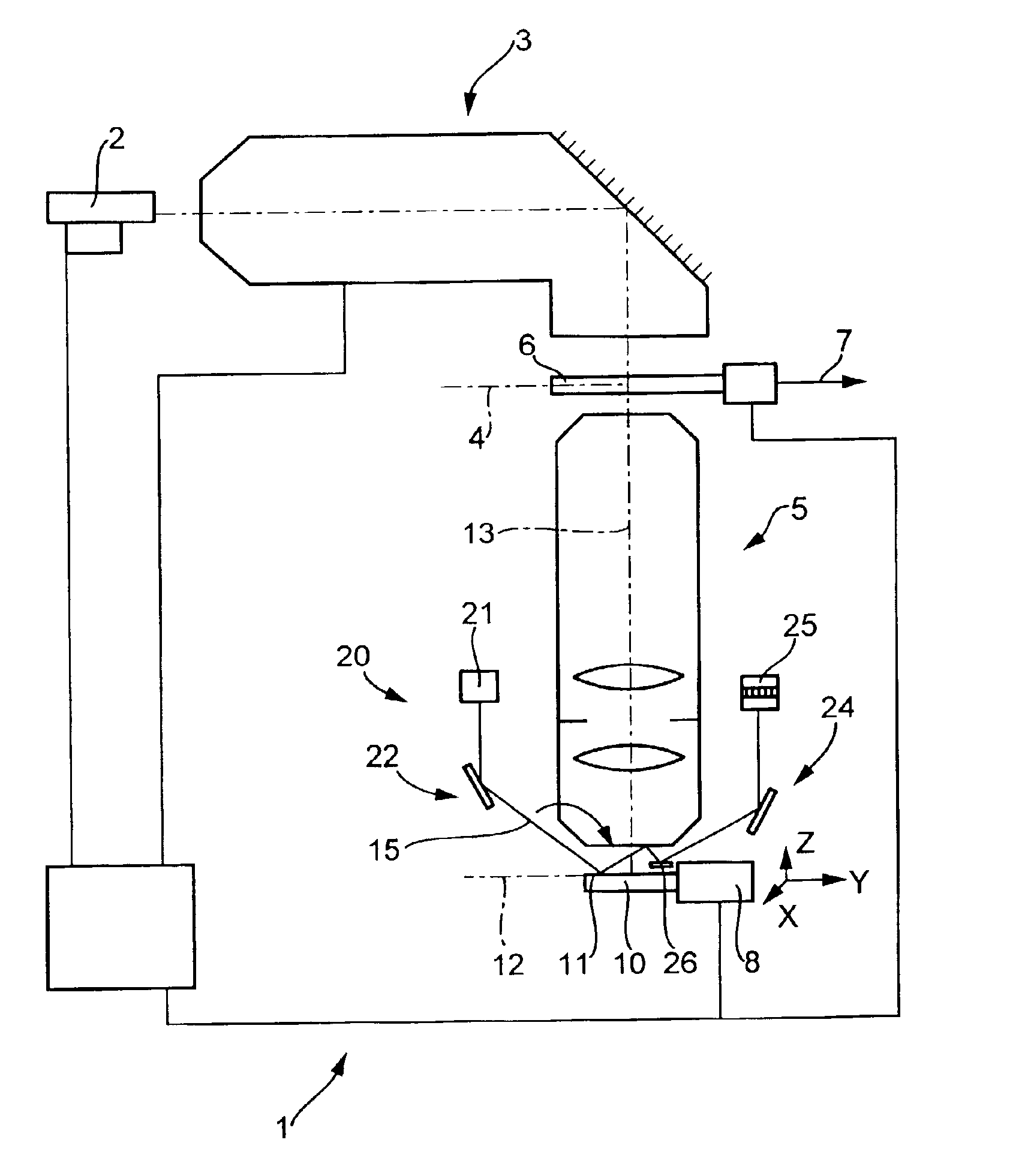
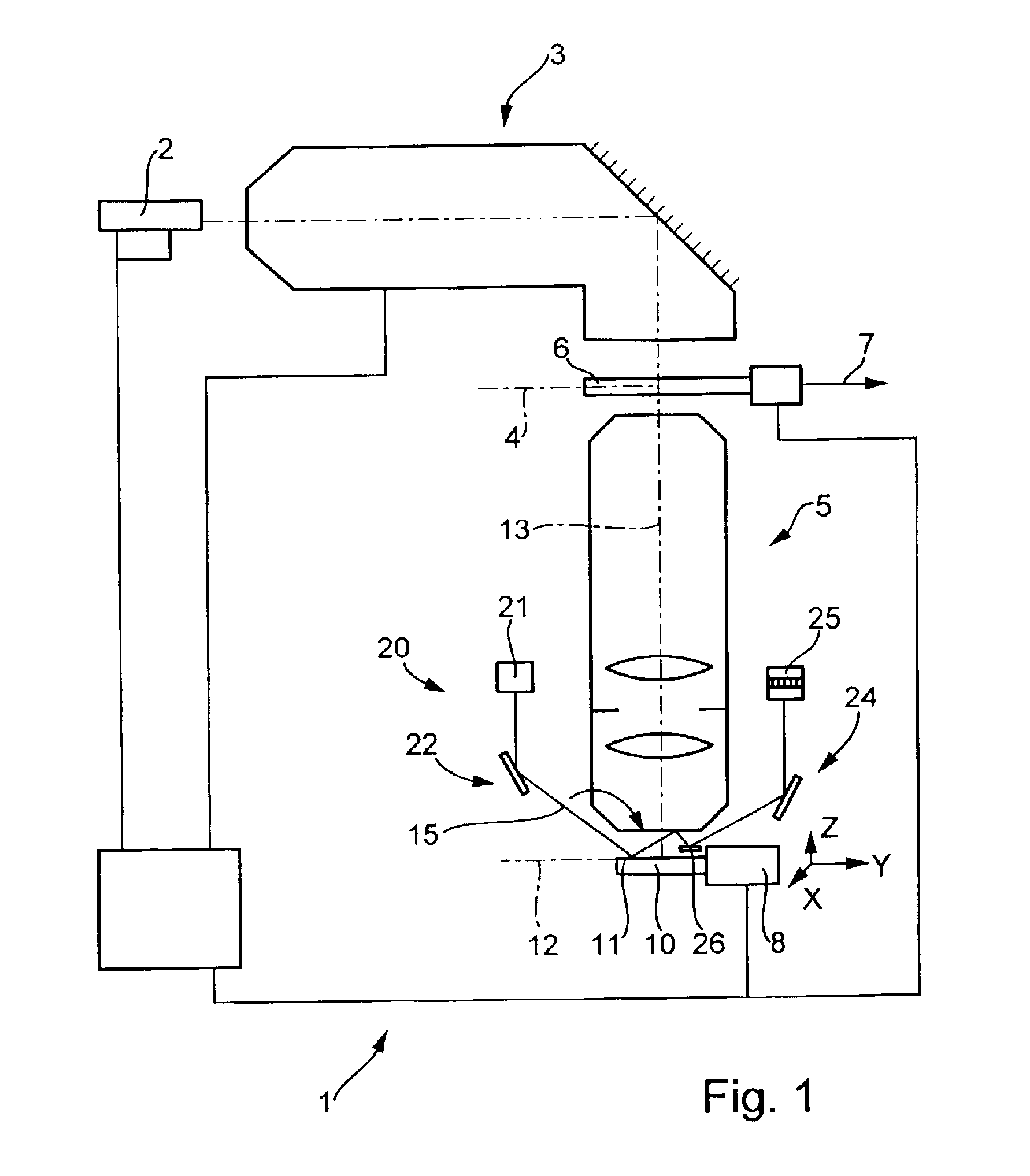
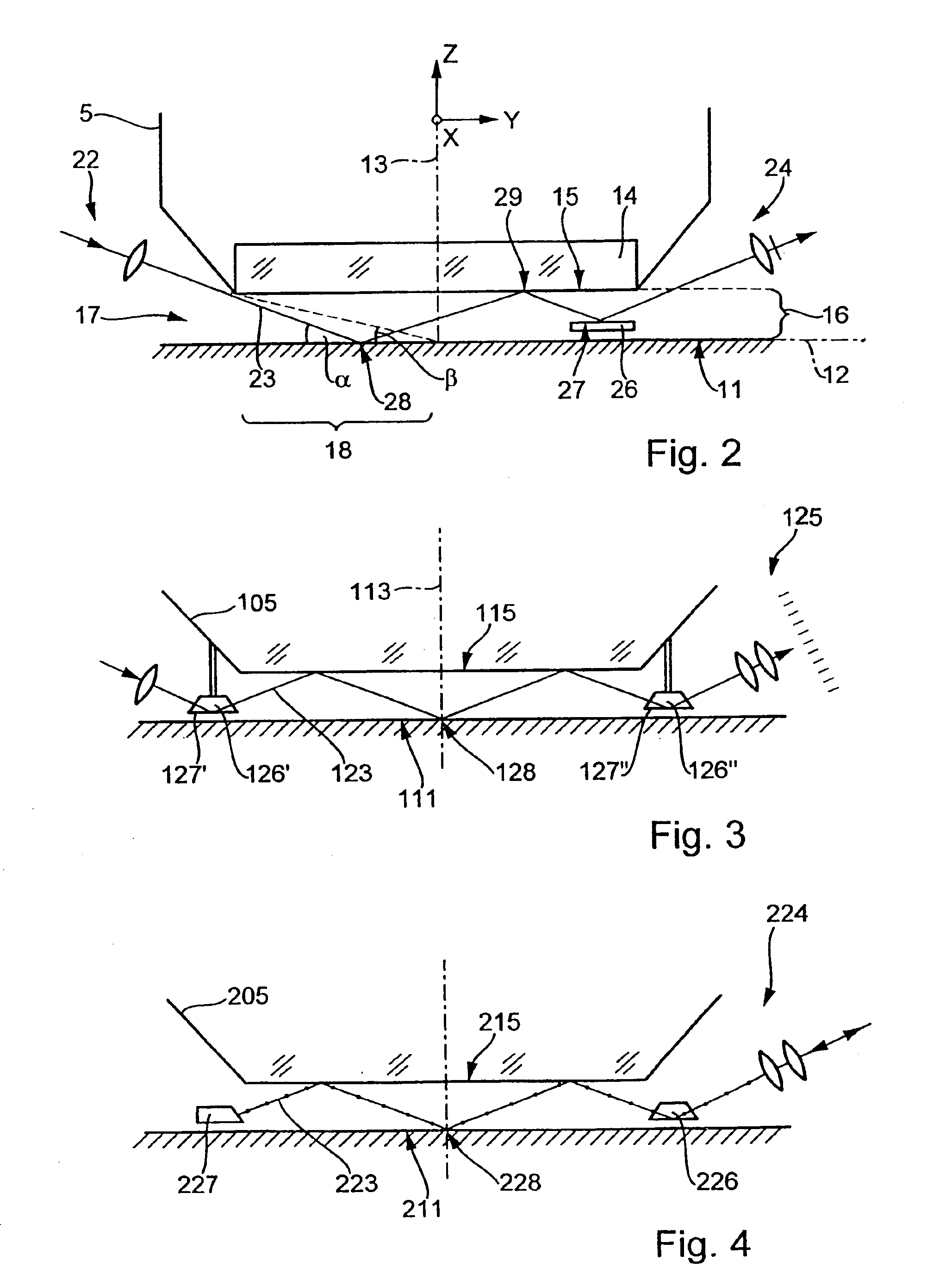
A second embodiment, wherein the focus-detection system utilizes a single reflection at the substrate's upper surface and two reflections at the exit surface of a projection lens will be discussed, based on FIG. 3. The layout of light source, input-coupling system, output-coupling system, and detector may be similar to, or identical to, the layout shown in FIG. 1. The system includes two prisms 126′ and 126″ whose reflective base surfaces 127′, 127″ are arranged outside the final surface 115 of the projection lens, in the space between the upper surface 111 of the substrate and the plane passing through the final surface of the lens 115, that are symmetrically arranged about the optical axis 113 and serve as auxiliary reflecting surfaces. These prisms 126′ and 126″ are rigidly attached to the lens' mount 105 and mounted a short distance above the upper surface 111 of the wafer. The system allows using a symmetric beam path for the measuring beam 123 that has a single reflection at t...

third embodiment

In the case of those systems shown in FIGS. 1 and 3, the light employed for measurement traverses the path traversed by the measuring beam once only. A third embodiment where the path traversed by the measuring beam is traversed twice will be discussed, based on FIG. 4. Its focus-detection system includes an optical system 224 that both couples the measuring beam 223 into the focus-detection system and couples it out of the focus-detection system. A prism 226 whose base surface is parallel to the image plane and serves as an auxiliary reflecting surface that obliquely deflects the light employed for measurement in the direction of the substrate's upper surface is arranged on the side of the input / output-coupling optics 224, between the plane of the planar exit surface 215 of the projection lens 205 and the upper surface 211 of the substrate. Following a total of two reflections at the exit surface 215 and a single reflection in the vicinity of the upper surface 211 of the substrate,...


PUM


Abstract

A microlithographic projection illumination system has a focus-detection system for optically detecting deviations of the image plane of a projection lens from the upper surface of a substrate arranged in the vicinity of its image plane. The focus-detection system has a system for coupling in at least one measuring beam that is obliquely incident on, and to be reflected at, the substrate surface into an intermediate zone between the final optical surface of the imaging system and the substrate surface and a system for coupling out the measuring beam and detecting it following its reflection at the substrate surface. The system for coupling the measuring beam in and the system for coupling it out are configured such that the measuring beam is reflected at least once at the substrate surface and at least once at a reflecting surface of the imaging system that reflects the light employed for measurement purposes before the measuring beam enters the system for coupling it out, which allows employing the image side of the imaging system as part of the focus-detection system. The focus-detection system also operates reliably when used on ultrahigh-aperture lenses that have correspondingly short working distances.

Description

The following disclosure is based on German Patent Application No. 102 29 818.1 filed on Jun. 28, 2002, which is incorporated into this application by reference.BACKGROUND OF THE INVENTION1. Field of the InventionThe invention relates to a method for optically detecting deviations of the image plane of an optical imaging system from the upper surface of a substrate to be arranged in the vicinity of that image plane and an imaging device, in particular, a projection exposure system for use in microlithography, that has an optical imaging system and a focus-detection system for carrying out the method.2. Description of the Related ArtProjection exposure systems for use in microlithography have been employed for fabricating semiconductor devices and other types of microdevices for several decades. They serve to image patterns on masks, or reticles, onto a substrate coated with a photosensitive layer at ultrahigh resolution, on a reduced scale, using an optical imaging system, their pro...

Claims


Application Information

Patent Timeline
IPC IPC(8): G03F9/00G02B7/28G01B11/00G03F7/20H01L21/027
CPCG03F9/7026G02B7/28
Inventor SCHUSTER, KARL-HEINZ
Owner CARL ZEISS SMT GMBH
Why Eureka
Try Eureka