Pulse radar detection system

a radar and pulse compression technology, applied in the field of pulse compression radar systems, can solve the problems of reducing the performance of the sensor, reducing the functional operation of the sensor, and increasing the cost of adding each additional circuit block

Inactive Publication Date: 2005-04-12
VEONEER US LLC
View PDF14 Cites 70 Cited by
  • Summary
  • Abstract
  • Description
  • Claims
  • Application Information

AI Technical Summary

Problems solved by technology

These prior art approaches can lead to a combination of manufacturing tolerance issues and operating scenarios that compromise the performance of the sensor.
The functional operation of the sensors is restricted for both size and cross constraints as each additional circuit block is relatively expensive to add.
This assumption no longer holds true under short pulse conditions, and can lead to transient and short-term circuit effects that reduce the operating margin and compromise sensor performance.
Lastly, the mid- to long-range operation of the short pulse sensor is not optimum due to two issues.
Conventionally, there are two limitations that restrict the amount of energy (power) that may be transmitted by the sensor: the ability to discriminate between two targets (range dis

Method used


Image

  • Pulse radar detection system
  • Pulse radar detection system
  • Pulse radar detection system

Examples


Embodiment Construction

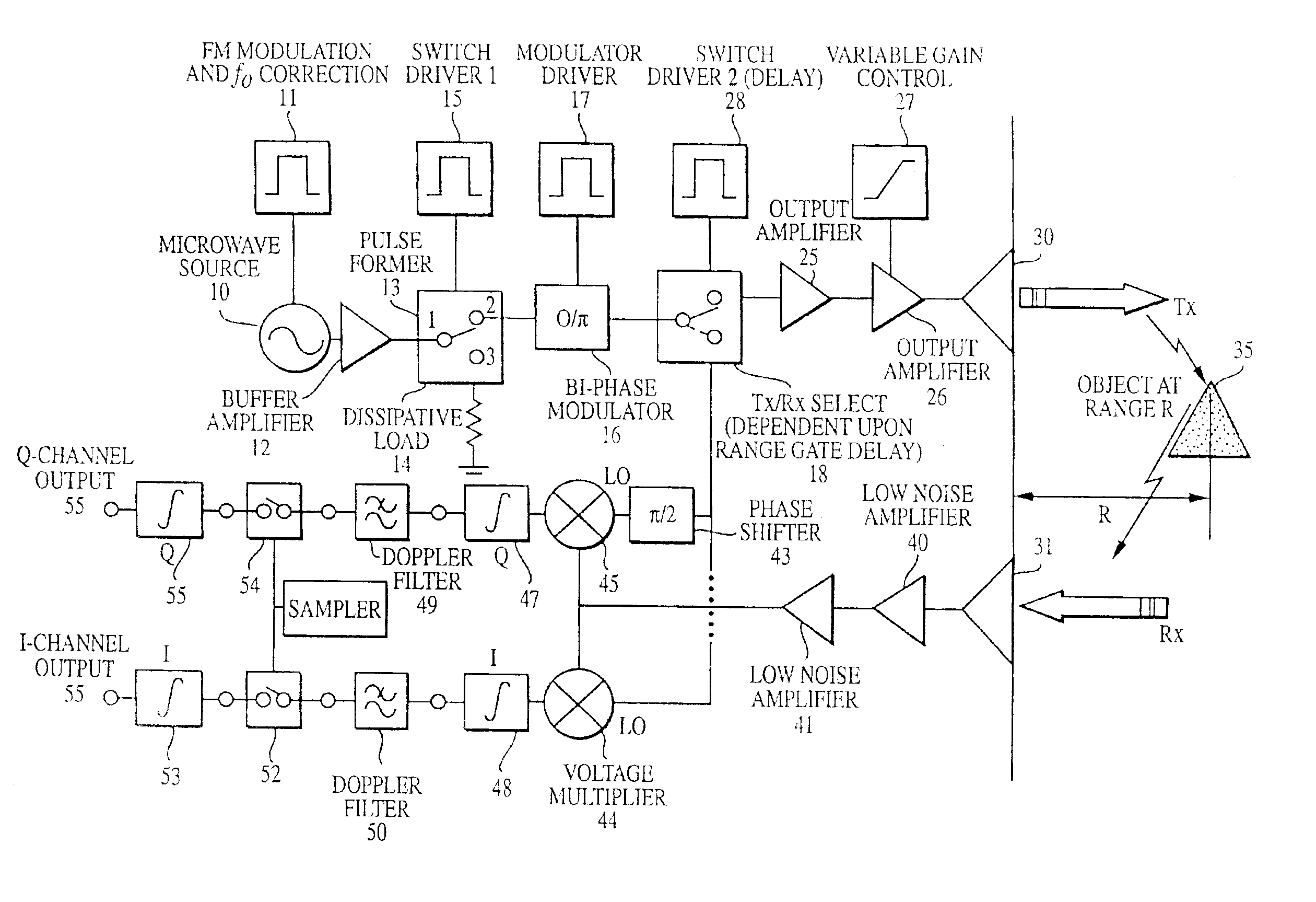
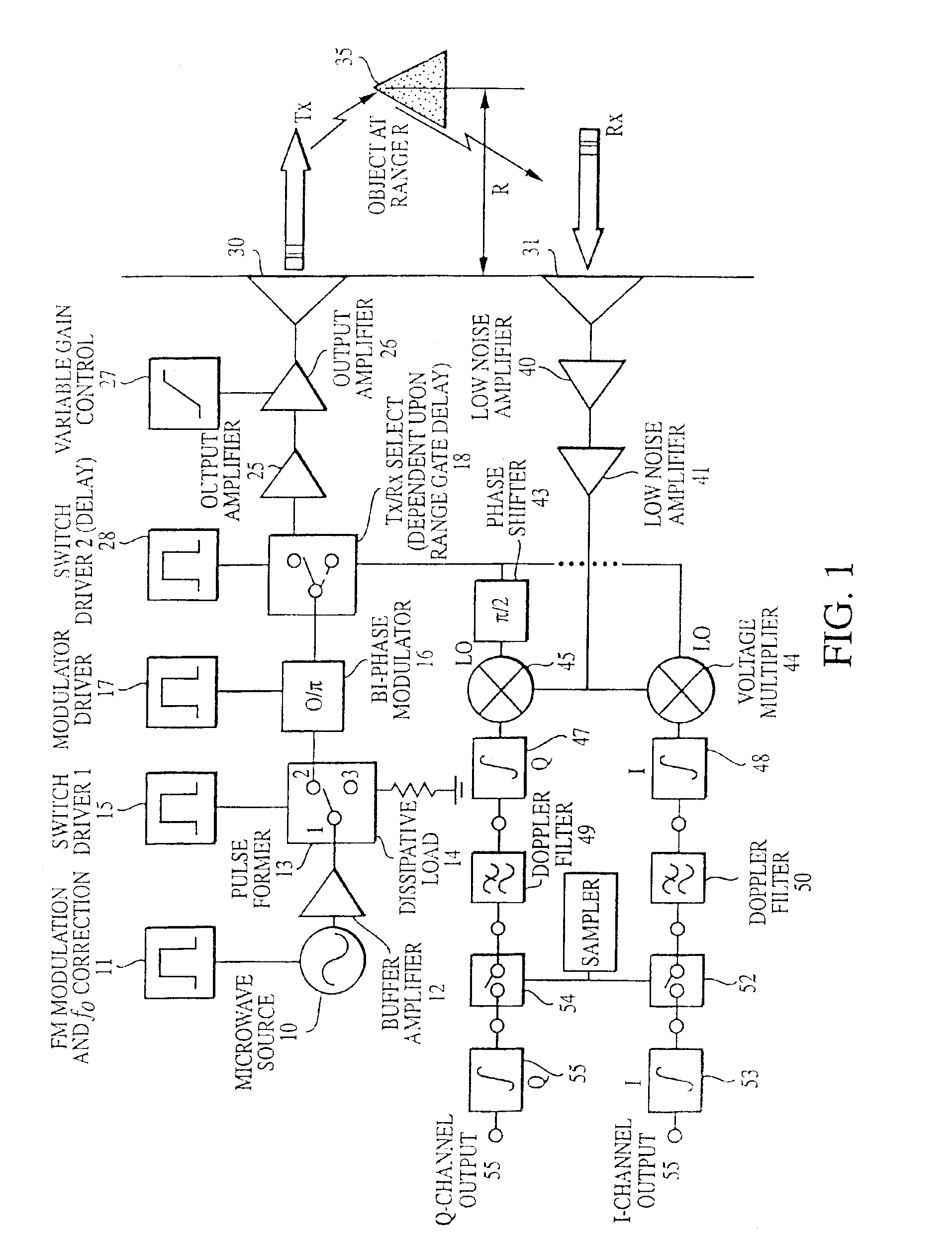
Referring to FIG. 1 there is shown a sensor architecture of a high-resolution radar (HRR) according to an aspect of the invention. The general principle of operation of a typical radar sensor is that of object detection, position and velocity measurement. In a typical radar, a carrier signal is transmitted from the sensor via an antenna. The antenna may be fixed, or steered where the focus of the beam may be dynamically varied by electronic, or mechanical control. In FIG. 1, there is shown a separate transmit antenna (Tx) 30 and a receive antenna (Rx) 31. Adjacent to the transmit antenna is an arrow designated Tx indicative of a transmitted signal. Similarly, there is an arrow showing a received signal at the receive antenna 31 designated as Rx. Thus, one can use a separate antenna for transmit and receive, but is also possible to use a single antenna to perform transmit and receive operation by adding additional switching elements without changing the principal of the described inv...


PUM


Abstract

A radar based sensor detection system comprises a microwave source operative to provide a continuous wave signal at an output. A pulse-former is coupled to the output of the source and is operative to provide at an output a variable length pulse that increases the transmitted energy of the radar system according to the range of object detection. A modulator is coupled to the output of the pulse-former for providing a modulated pulse signal when required. A transmit/receive switch coupled to the output of the modulator is selectively operative between a first transmit position and a second receive position. A transmit channel coupled to the transmit/receive switch transmits the pulse signal when the switch is operated in the transmit position. A receiving channel coupled to the transmit/receive switch receives the modulator signal when the switch is operated in the receive position. First and second voltage multipliers each have a local oscillator input for receiving the modulator signal in the receive position, and each have an input signal port, and an output port. A receiver channel receives a reflected transmitted signal from an object and applies the received signal to the receive signal input ports of the voltage multipliers. An autocorrelator coupled to the output ports of the voltage multipliers correlates the received signal to produce an output signal indicating the detection and position of the object.

Description

FIELD OF INVENTIONThis invention relates to a short-range pulse-compression radar system particularly suitable for fabrication as an integrated circuit.BACKGROUND OF INVENTIONA need exists for a short-range radar system, which, for example, is suitable for automotive and other commercial applications. Such a system would be enabled to sense the proximity of other vehicles and objects, moving or stationary, within a range radius of about 0.15 meters to 30 meters or beyond. Radar systems having automotive application have been proposed in the prior art, including systems utilizing radar for automatic braking, as well as warning the operator of the vehicle of an impending danger or obstruction such as an animal or person in the roadway.In addition to object range detection, it is also useful to be able to distinguish or resolve the distance between two objects in very close proximity (e.g. when they are approximately 15 centimeters apart). An intelligent radar detection system comprise...

Claims


Application Information

Patent Timeline
IPC IPC(8): G01S13/18G01S13/00G01S13/28G01S13/10G01S7/28G01S7/288G01S7/282G01S7/285G01S13/26
CPCG01S7/282G01S7/288G01S13/18G01S13/288G01S13/106G01S2007/2886G01S7/2886G01S13/32
Inventor GRESHAM, ROBERT IANEGRI, ROBERT
Owner VEONEER US LLC
Why Eureka
Try Eureka