Packaged integrated antenna for circular and linear polarizations

a dielectric resonator and integrated antenna technology, applied in the direction of antennas, radiating element structural forms, electrical devices, etc., can solve the problems of low forward-to-backward ratio, low radiation efficiency of conventional integrated patch antennas, and compact and fully integrated antenna design, etc., to achieve simple feed design and simple feed design

Inactive Publication Date: 2005-04-12
AGENCY FOR SCI TECH & RES
View PDF12 Cites 14 Cited by
  • Summary
  • Abstract
  • Description
  • Claims
  • Application Information

AI Technical Summary

Benefits of technology

[0016]Yet another objective of the invention is to provide circular polarized radiation from a dielectric resonator antenna with a simple feed design.
[0017]Yet another objective of the invention is to provide circular polarized radiation from a dielectric resonator antenna with a simple feed design where the feed and the dielectric resonator are formed on the same plane.
[0019]Yet another objective is to provide a linear polarized radiation from a dielectric resonator antenna and to achieve a wider impedance bandwidth with a simple feed design.
[0021]Also in accordance with the objectives of the invention, a circular polarized radiation dielectric resonator antenna with a simple feed design is achieved. The dielectric resonator antenna comprises a feed substrate having an upper and a lower surface, a first ground plane formed on the upper surface of the feed substrate and a second ground plane formed on the lower surface of the feed substrate, a dielectric resonator attached to the first ground plane, an asymmetrical feed structure formed on the first ground plane wherein the asymmetrical feed structure excites modes in the dielectric resonator in orthogonal directions to provide circular polarized radiation, and radio frequency circuitry mounted on the lower surface of the feed substrate and coupled to the feed structure.
[0022]Also in accordance with the objectives of the invention, a linear polarized radiation dielectric resonator antenna with a simple feed design is achieved. The dielectric resonator antenna comprises a feed substrate having an upper and a lower surface, a first ground plane formed on the upper surface of the feed substrate and a second ground plane formed on the lower surface of the feed substrate, a dielectric resonator attached to the first ground plane, a feed structure formed on the first ground plane wherein the feed structure comprises both magnetic and electric dipoles to provide linear polarized radiation, and radio frequency circuitry mounted on the lower surface of the feed substrate and connected to the feed structure by a via through the feed substrate.

Problems solved by technology

Design of compact and fully integrated antennas is a major challenge in the development of modern radio frequency (RF) front end products for wireless communications.
Due to natural physical limitations on the RF system dimensions, an integrated antenna has, as usual, small electrical size and must operate with a finite “ground plane”, which has a great influence on the return loss and may result in a low forward-to-backward ratio.
The conventional integrated patch antennas suffer from low radiation efficiency, high sensitive fabrication tolerances, and narrow bandwidth.
The drawbacks of this solution are mainly the narrow impedance bandwidth of 0.67% and relatively high return loss of −6 dB within the operating bandwidth.
The paper's proposed solution also exhibits low forward-to-backward ratio (FIG. 2) that may result in a feedback to the sensitive circuitry of the RF system.
However, the solutions for integrated dielectric resonator antennas in RF systems in packages have not yet been disclosed.
Also, the available feed designs for dielectric resonator antennas with circular / linear polarized radiation are not convenient for the antenna integration in RF systems in packages and have some drawbacks in terms of available bandwidth and limitations on the ground plane size.
The drawbacks of this solution are the requirement of drilling holes in the dielectric resonator, difficulties of the antenna integration, and / or narrow impedance bandwidth achievable.
The drawbacks of this solution are a complicated feed design and higher losses in the splitter (FIG. 3) and phase shifting circuitry.
Also, the power splitting and phase shifting circuitry requires considerable space on the printed circuit board (PCB) and thus complicates the antenna integration into the RF system in the package.
The drawback of this solution is the requirement for the dielectric resonator metallization and difficulties in the antenna tuning to compensate for the fabrication tolerances.
The drawback of this solution is a strict limitation on dielectric resonator fabrication tolerances and a limited bandwidth for an acceptable level of the axial ratio of the antenna.

Method used


Image

  • Packaged integrated antenna for circular and linear polarizations
  • Packaged integrated antenna for circular and linear polarizations
  • Packaged integrated antenna for circular and linear polarizations

Examples


Embodiment Construction

nal representation of a dielectric resonator antenna with linear polarization of the present invention.

[0034]FIG. 9B is a top view of FIG. 9A.

[0035]FIG. 10 is a cross-sectional representation of a multi layer dielectric resonator package of the present invention.

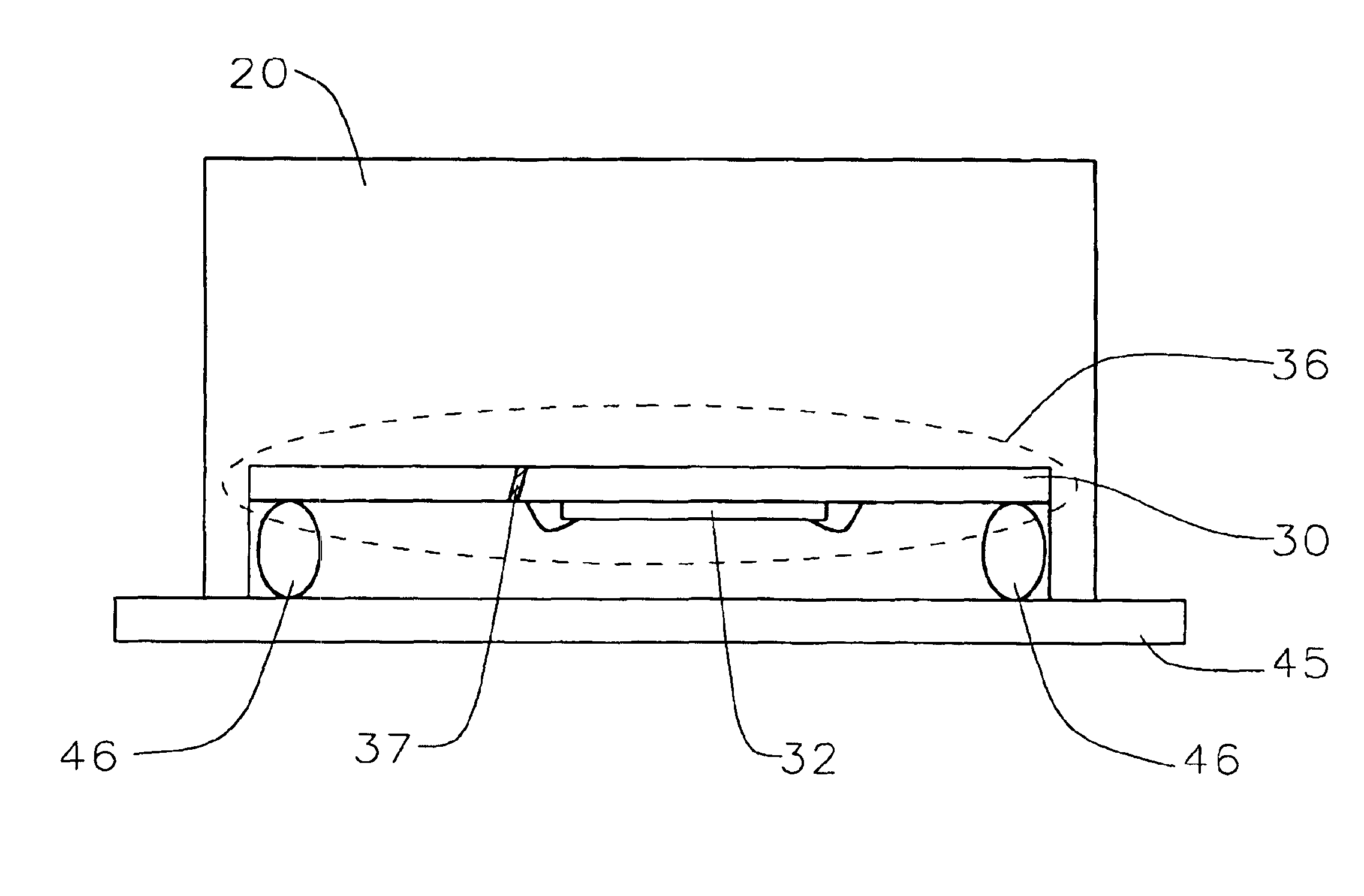
[0036]FIG. 11A is a cross-sectional representation of a dielectric resonator package of the present invention.

[0037]FIG. 11B is a top view of FIG. 11A.

[0038]FIG. 12 is a cross-sectional representation of a dielectric resonator package of the present invention.

[0039]FIG. 13 is a cross-sectional representation of a stand alone dielectric resonator package of the present invention.

[0040]FIG. 14 is a cross-sectional representation of a dielectric resonator package of the present invention on a printed circuit board.

DESCRIPTION OF THE PREFERRED EMBODIMENTS

[0041]A conventional radio frequency (RF) package serves to protect RF circuitry inside the package from the environment hazards, for thermal management and to provide an electr...


PUM


Abstract

A high radiation efficiency antenna system in a package is achieved by the provision of a Dielectric Resonator Package. A Dielectric resonator package comprises a dielectric body of the package forming a dielectric resonator that resonates at radio frequency and a feed substrate having an upper and a lower surface, a feed structure formed on the upper surface of the feed substrate, and RF circuitry mounted on the lower surface of the feed substrate. The feed substrate is attached to the dielectric body of the package from the side of the feed structure.

Description

BACKGROUND OF THE INVENTION[0002](1) Field of the Invention[0003]The invention relates to the dielectric resonator antennas and, more particularly, to packaged dielectric resonator antennas having circular and linear polarizations and high radiator efficiency.[0004](2) Description of the Prior Art[0005]Design of compact and fully integrated antennas is a major challenge in the development of modern radio frequency (RF) front end products for wireless communications. Due to natural physical limitations on the RF system dimensions, an integrated antenna has, as usual, small electrical size and must operate with a finite “ground plane”, which has a great influence on the return loss and may result in a low forward-to-backward ratio. The conventional integrated patch antennas suffer from low radiation efficiency, high sensitive fabrication tolerances, and narrow bandwidth. In particular, in Song, C. T. P. et al, “Packaging technique for gain enhancement of electrically small antenna des...

Claims


Application Information

Patent Timeline
Patent Type & Authority Patents(United States)
IPC IPC(8): H01Q1/38H01Q9/04
CPCH01Q1/38H01Q9/0492H01Q9/0485H01L2223/6627H01L2223/6677H01L2224/16227H01L2224/48091H01L2224/48227H01L2224/48235H01L2924/15153H01L2924/15321H01L2924/19107
Inventor POPOV, ALEXANDER PAVLOVICHROTARU, MIHAI DRAGOSIYER, MAHADEVAN KRISHNA
Owner AGENCY FOR SCI TECH & RES
Why Eureka
Try Eureka