
Digital camera system containing a VLIW vector processor

a vector processor and camera system technology, applied in the field of digital image processing, can solve the problems of not being able to detect if the data retrieved from the card is correct, not allowing for the fact that ink can fade, and parts of the card may be damaged with dirt, grime, or even scratches,

Inactive Publication Date: 2005-04-12
GOOGLE LLC
View PDF11 Cites 186 Cited by
  • Summary
  • Abstract
  • Description
  • Claims
  • Application Information

AI Technical Summary

Benefits of technology

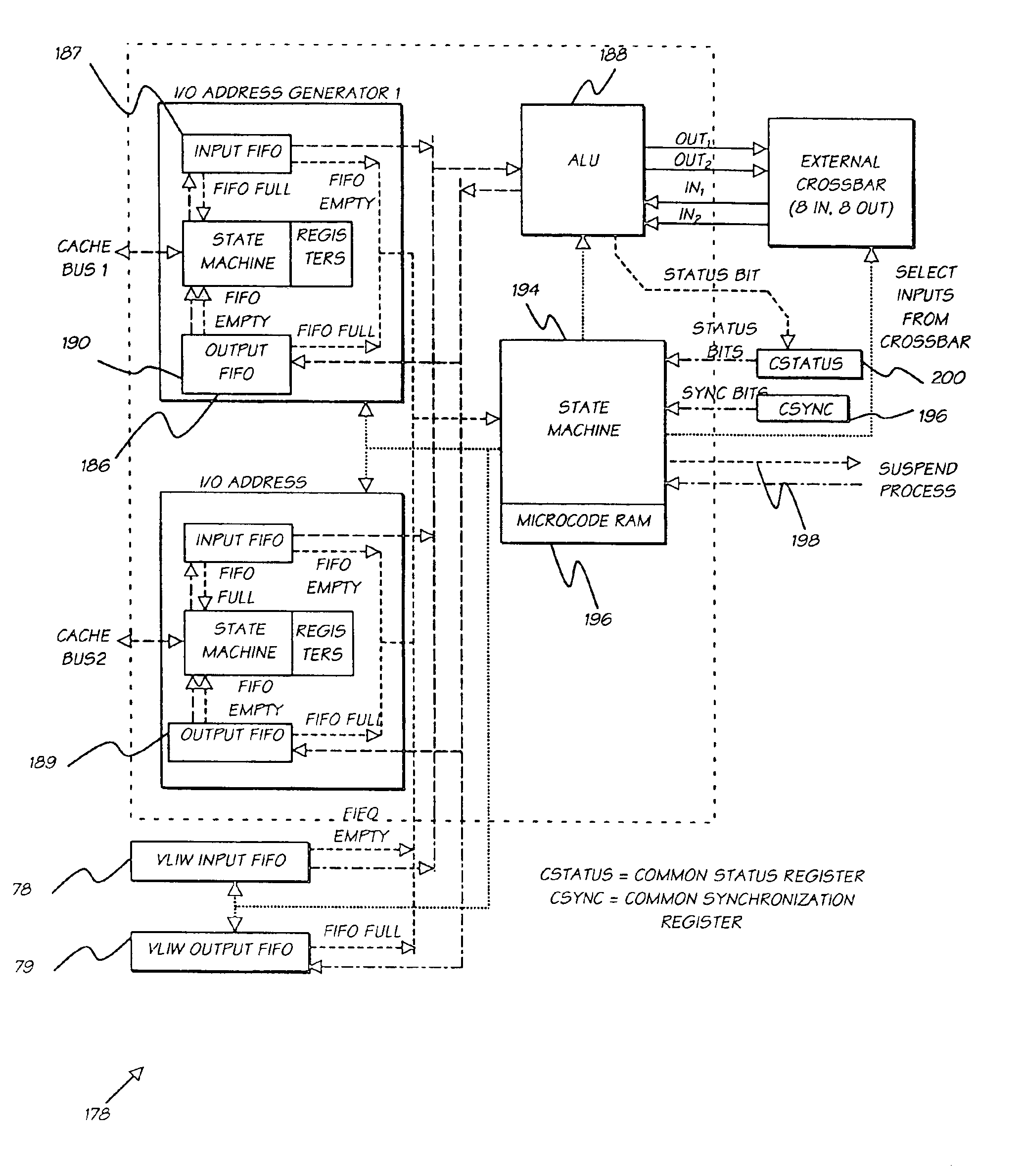
In accordance with a first aspect of the present invention, there is provided a digital camera system comprising a sensing means for sensing an image; modification means for modifying the sensed image in accordance with modification instructions input into the camera; and an output means for outputting the modified image; wherein the modification means includes a series of processing elements arranged around a central crossbar switch. Preferably, the processing elements include an Arithmetic Logic Unit (ALU) acting under the control of a microcode store wherein the microcode store comprises a writeable control store. The processing elements can include an internal input and output FIFO for storing pixel data utilized by the processing elements and the modification means is interconnected to a read and write FIFO for reading and writing pixel data of images to the modification means.

Problems solved by technology

This scheme however, does not allow for the fact that ink can fade, parts of a card may be damaged with dirt, grime, or even scratches.
Without error-detection encoding, there is no way to detect if the data retrieved from the card is correct.
And without redundancy encoding, there is no way to correct the detected errors.
Any dirt, grime, or stain that causes physical damage to the card has the potential of damaging more than 64 bytes in a single Reed-Solomon block, which would make that block unrecoverable.
Under this scrambling scheme, complete damage to 16 entire data blocks on the alternative Artcard will result in 64 symbol errors per Reed-Solomon block.
It is extremely unlikely that a user will insert an alternative Artcard into an alternative Artcard reader perfectly aligned with no rotation.
This is made more problematic by the effects of rotation.
There is a trade-off between algorithmic complexity, user perceived delays, robustness, and memory usage.
Not only would this require huge reserves of memory, it would take longer than a reader algorithm that occurred concurrently with the alternative Artcard reading process.
Alternative Artcards may be scratched, or be stained with grime or dirt.
The effect of dirty data is made worse by blurring, as the dirty data affects the surrounding clean dots.
However if the area covered by a CCD pixel is too large, there will be too much blurring and the sampling required to recover the data will not be met. FIG. 64 is a schematic illustration of the overlapping of sensed data.
Another form of blurring occurs when an alternative Artcard is slightly warped due to heat damage.
Blurring can cause problems in attempting to determine whether a given dot is black or white.
However the greater the blurring, the more the two curves shift towards the center of the range and therefore the greater the intersection area, which means the more difficult it is to determine whether a given dot is black or white.
As the blurring increases, the likelihood of a read bit error increases.
Of course, with block duplication the chance of an alternative Artcard decoding increases.
If Process 3 has not finished by that time, the data from the alternative Artcard cannot be recovered.
In addition, the target numbers recovered from the targets may be in error.
It may be that the clockmark or border has been damaged in some way—perhaps it has been scratched.
One of the reasons the card is divided into 8 data blocks high is that we cannot make the same rigid guarantee across the entire height of the card that we can about a single data block.
These schemes must balance complexity against accuracy, and also take into account the fact that in some cases, there is no guaranteed solution.
Thus each target evaluation consumes the time taken by otherwise processing a row of pixels.
This has implications for the Process Targets process in that the processing of targets can be performed by a relatively inefficient method if necessary, yet still catch up quickly during the extracting data process.
Unfortunately, the utilization of arbitrarily sized warp maps presents a number of problems which must be solved by the image warper.
Unfortunately, any output image eg.
Since a single output pixel could theoretically be represented by the entire input image, it is potentially too time-consuming to actually read and average the specific area of the input image contributing to the output pixel.
Performing linear interpolation between two levels of the image pyramid is not strictly correct, but gives acceptable results (it errs on the side of blurring the resultant image).
However, access to 3 conversion tables equals ⅓ of the caching for each, that could lead to high latency for the overall process.

Method used


Image

  • Digital camera system containing a VLIW vector processor
  • Digital camera system containing a VLIW vector processor
  • Digital camera system containing a VLIW vector processor

Examples


case 1

BlackDetectCount[target]< 8Δ := ABS(S2StartPixel −ORPrevColStartPixel[Target])WhiteDetectCount[Target] = 0If (0<=Δ<2)BlackDetectCount[Target]++(max value =8)ElseBlackDetectCount[Target] := 1WhiteDetectCount[Target] := 0EndIfPrevColStartPixel[Target] :=S2StartPixelColumnDetected[Target] :=TRUEBitDetected = 1BlackDetectCount[target]>= 8PrevColStartPixel[Target] :=WhiteDetectCount[Target] != 0S2StartPixelColumnDetected[Target] :=TRUEBitDetected = 1TargetDetected[Target] :=TRUETargetColumn[Target] :=CurrentColumn − 8 −(WhiteDetectCount[Target] / 2)

case 2

No special processing is recorded except for setting the ‘PrevCaseWasCase2’ flag for identifying Case 3 (see Step 3 of processing a column described above).

case 3

PrevCaseWasCase2 = TRUEIf (WhiteDetectCount[Target]< 2)BlackDetectCount[Target]>= 8TargetRow[Target] =WhiteDetectCount=1S2StartPixel +(S2RunLength / 2)EndIfΔ := ABS(S2StartPixel −PrevColStartPixel[Target])If (0<=Δ< 2)WhiteDetectCount[Target]++ElseWhiteDetectCount[Target] := 1EndIfPrevColStartPixel[Target] :=S2StartPixelThisColumnDetected := TRUEBitDetected = 0

At the end of processing a given column, a comparison is made of the current column to the maximum number of columns for target detection. If the number of columns allowed has been exceeded, then it is necessary to check how many targets have been found. If fewer than 8 have been found, the card is considered invalid.

Process Targets

After the targets have been detected, they should be processed. All the targets may be available or merely some of them. Some targets may also have been erroneously detected.

This phase of processing is to determine a mathematical line that passes through the center of as many targets as ...


PUM


Abstract

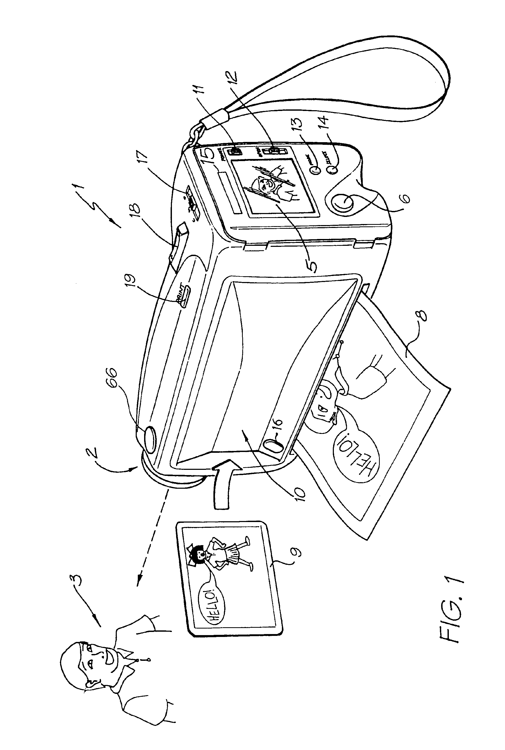
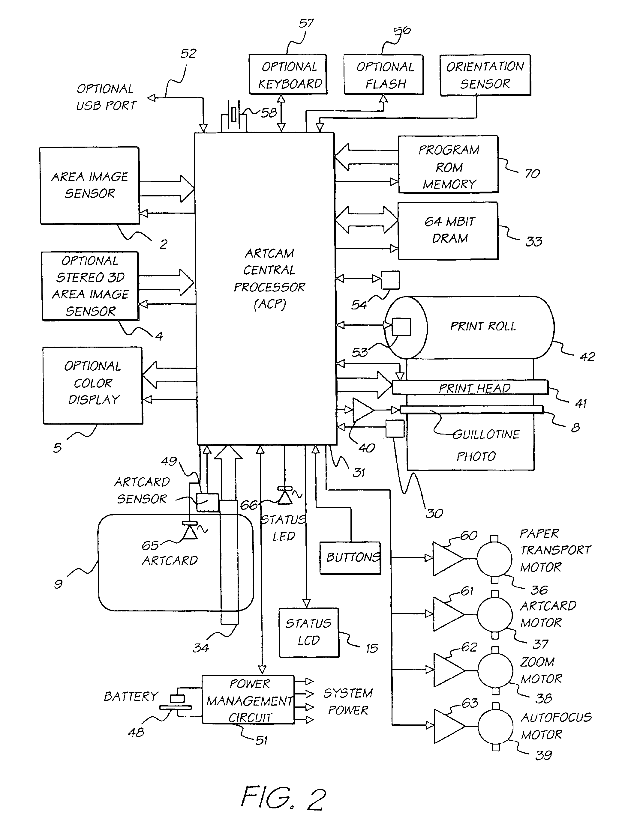
A digital camera has a sensor for sensing an image, a processor for modifying the sensed image in accordance with instructions input into the camera and an output for outputting the modified image where the processor includes a series of processing elements arranged around a central crossbar switch. The processing elements include an Arithmetic Logic Unit (ALU) acting under the control of a writeable microcode store, an internal input and output FIFO for storing pixel data to be processed by the processing elements and the processor is interconnected to a read and write FIFO for reading and writing pixel data of images to the processor. Each of the processing elements can be arranged in a ring and each element is also separately connected to its nearest neighbors. The ALU receives a series of inputs interconnected via an internal crossbar switch to a series of core processing units within the ALU and includes a number of internal registers for the storage of temporary data. The core processing units can include at least one of a multiplier, an adder and a barrel shifter. The processing elements are further connected to a common data bus for the transfer of a pixel data to the processing elements and the data bus is interconnected to a data cache which acts as an intermediate cache between the processing elements and a memory store for storing the images.

Description

FIELD OF THE INVENTIONThe present invention relates to digital image processing and in particular discloses Camera System Containing a VLIW Vector Processor.Further the present invention relates to an image processing method and apparatus and, in particular, discloses a Digital Instant Camera with Image Processing Capability.The present invention further relates to the field of digital camera technology and, particularly, discloses a digital camera having an integral color printer.BACKGROUND OF THE INVENTIONTraditional camera technology has for many years relied upon the provision of an optical processing system which relies on a negative of an image which is projected onto a photosensitive film which is subsequently chemically processed so as to “fix” the film and to allow for positive prints to be produced which reproduce the original image. Such an image processing technology, although it has become a standard, can be unduly complex, as expensive and difficult technologies are in...

Claims


Application Information

Patent Timeline
Patent Type & Authority Patents(United States)
IPC IPC(8): B41J15/04B41J11/00B41J11/70B41J2/14B42D15/10B41J2/175B41J2/16B41J3/42G06F1/16G06K1/00G06K1/12G11C11/56G06F21/00G07F7/08G06K19/073G07F7/12G06K19/06G06K7/14H04N5/225H04N1/21H04N5/262H04N1/32B41J2/165H04N1/00H04N25/00B41J3/44H04N23/40
CPCB41J2/14314H04N5/378B41J2/17513B41J3/445B41J11/0005B41J11/70B41J15/04B82Y30/00G06F9/226G06F9/265G06F9/30094G06F9/30101G06F9/3885G06F21/79G06F21/86G06K1/121G06K7/10762G06K7/14G06K7/1417G06K19/06037G06K19/073G11C11/56H01L23/576H04N1/00326H04N1/0044H04N1/00965H04N1/00968H04N1/2112H04N1/2154H04N1/32101H04N1/32133H04N1/32561H04N1/32587H04N1/32593H04N1/32603H04N5/225H04N5/2628H04N1/00278H04N5/23229B41J2/14427B41J2/16585B41J2/17596B41J2002/041B41J2202/21G06F7/57G06F2221/2129H04N1/00127H04N2101/00H04N2201/0008H04N2201/0084H04N2201/3222H04N2201/3261H04N2201/3264H04N2201/3269H04N2201/3276H04N2201/328H01L2924/0002H01L2924/00H04N1/46H04N5/76G06K15/00G06F15/00H04N23/00H04N23/40H04N23/70H04N23/80H04N25/75B41J11/005
Inventor SILVERBROOK, KIA
Owner GOOGLE LLC
Learn More