
Quick layer-3 message multiplexing

a message multiplexing and layer 3 technology, applied in the field of wireless communication, can solve the problems of prone to some problems in the partitioning of functionality into layers, and reducing so as to reduce the buffering or queuing time, reduce the processing time of message flows, and reduce the delay of the path

Inactive Publication Date: 2005-04-12
CISCO TECH INC
View PDF19 Cites 52 Cited by
  • Summary
  • Abstract
  • Description
  • Claims
  • Application Information

AI Technical Summary

Benefits of technology

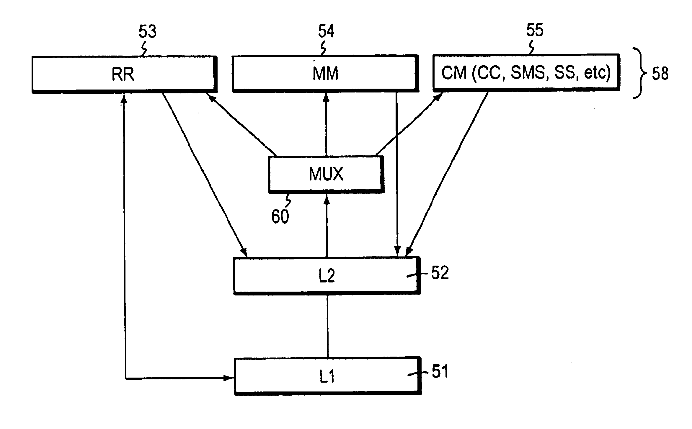
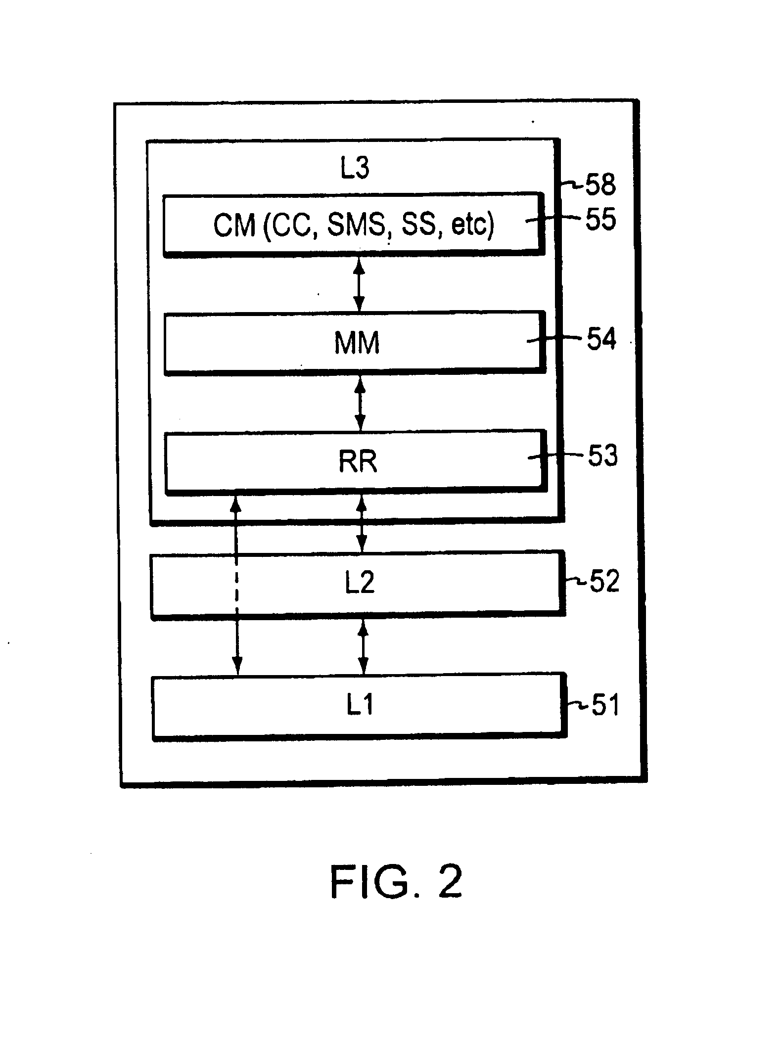
The present invention seeks to eliminate some of the disadvantages of a standard GSM-type implementation by flattening the Layer 3 stack model. In this architecture, a centralized multiplex function processes all Layer 3 messages, dispatching them to the Radio Resource management (RR), Mobility Management (MM), or Connection Management (CM) functional layer as appropriate.
The present invention has several advantages. The centralized multiplex function reduces the processing time for processing message flows from Layer 2 towards Layer 3 functions. By reducing this path delay, less buffering or queuing time is needed, therefore decreasing the time needed to complete end-to-end processing of mobility-related and call processing messages. In addition, eliminating multiplex functionality entirely in the downlink direction also speeds processing. For such time-critical procedures such as location update, handover, and cell reselection, implementation of the present invention improves overall system performance and reliability. The speed improvement is also carried forward to call processing procedures as well.

Problems solved by technology

While the Global System for Mobile (GSM) standard specifies an elegant division of functionality according to the OSI layered protocol reference model, this partitioning of functionality into layers is prone to some problems in some instances.
When the mobile station is moving rapidly such as in an automobile, any delays associated with completing Layer 3 functions may result in delays in setting up and placing calls.
In the worst case, they can result in dropped calls when messages are not processed within certain timing restrictions.

Method used


Image

  • Quick layer-3 message multiplexing
  • Quick layer-3 message multiplexing
  • Quick layer-3 message multiplexing

Examples


Embodiment Construction

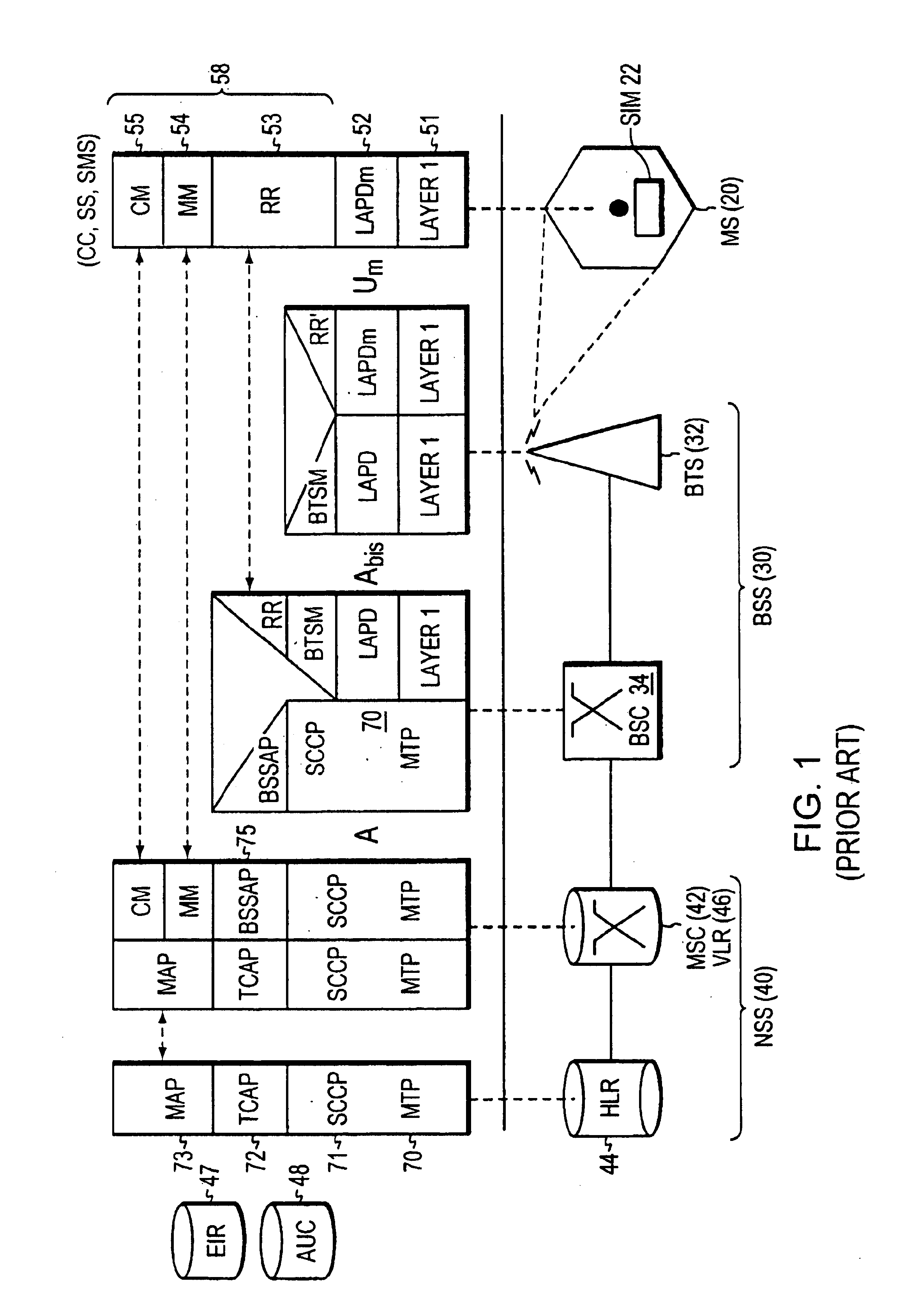
Turning attention to FIG. 1, the functional architecture of a GSM system 10 can be broadly divided into subsystems including a mobile station (MS) 20, a Base Station Subsystem (BSS) 30, and a Network Sub-System (NSS) 40. Each subsystem is comprised of functional entities which communicate through various interfaces using protocols specified by the GSM standard.

The mobile station 20 in GSM is really two distinct entities. The actual hardware is the mobile equipment, which is the equipment which the subscriber or user carries. Subscriber information, which includes a unique identifier called the International Mobile Subscriber Identity (IMSI), is stored in a Subscriber Identity Module (SIM) 22, typically implemented as a smart card. By inserting the SIM card in any GSM mobile equipment, a user is able to make and receive calls at that terminal and receive other services to which the user has subscribed. By decoupling subscriber information from a specific terminal, greater personal mo...


PUM


Abstract

A technique for implementing a flattened Layer 3 stack model within a Global System for Mobile (GSM) communication system so that a centralized multiplex function associated with certain functions handles messages. The multiplex function dispatches radio resource (RR), mobility management (MM), or Connection Management (CM) function messages directly to the respective functional layers without first requiring such messages to pass through a stack. In the preferred arrangement, the multiplex function sub-L3 handles only uplink messages, allowing downlink messages to travel through the sub-layer stack without employing any bridging entity. The multiplex function can run independently of any of the other functions in Layer 3 or can be implemented as part of the message passing part of the Layer 2 running body so that the Layer 2 messages are routed directly to a respective RR, MM, or CM function. The flattened protocol stack permits time-sensitive messages related to location update, handover, or cell reselection and other time-critical messages to be handled more efficiently.

Description

BACKGROUND OF THE INVENTIONThe present invention relates generally to wireless communications and in particular to a technique for implementing network layer message multiplexing.Trends in wireless communication systems such as cellular mobile telephone systems, Personal Communication Services (PCS) systems, and the like, for the most part continue to suggest digital techniques are preferred for radio modulation. Although competing standards have been implemented in certain areas, the Global System for Mobile (GSM) communication is the most widely implemented system in the world.The architecture of a GSM system can be broadly divided into three subsystems, including a Mobile Station, a Base Station Subsystem, and a Network Sub-System. The mobile station (MS) is the portable subscriber or user equipment with which most people are familiar. The Base Station Subsystem (BSS) is typically considered to be composed of two parts, a Base Transceiver Station (BTS) and a Base Station Controll...

Claims


Application Information

Patent Timeline
IPC IPC(8): H04B7/212H04W4/18H04W76/04
CPCH04W76/04H04W4/18H04W76/20
Inventor XU, XIAODEYANG, SHEAUSONGNELAKANTI, BHAVANNARAYANA SRI NRUSIMHASAYERS, IANHUANG, WENFENG
Owner CISCO TECH INC
Learn More