Method for estimating fuel injector performance

a fuel injector and performance estimation technology, applied in the direction of electrical control, process and machine control, instruments, etc., can solve the problems of different delay periods of fuel injectors, engine performance problems, engine generation of unequal torque, etc., and achieve the effect of reducing the determined error

Inactive Publication Date: 2005-04-12
CATERPILLAR INC
View PDF32 Cites 29 Cited by
  • Summary
  • Abstract
  • Description
  • Claims
  • Application Information

AI Technical Summary

Benefits of technology

Another aspect of the present invention is directed to a method of identifying a set of test rail pressures for a fuel injector. An actual injection delay is measured for each of a plurality of fuel injectors at a first set of rail pressures. A baseline injection delay curve for the plurality of fuel injectors is determined based on the measured actual injection delays at each of the first set of rail pressures. An injection delay for each of the plurality of fuel injectors is es

Problems solved by technology

In addition, the different response characteristics of the individual fuel injectors may result in each fuel injector having a different delay period between the application of the control signal and the start of fuel injection.
An engine may experience performance problems if the amount and/or timing of fuel delivered to each combustion chamber diverges from an acceptable tolerance range.
For example, the engine may generate an unequal amount of torque when the amount of fuel delivered to one combustion chamber is greater than the amount of fuel delivered to another combustion chamber in the engine.
The unequal torque may result in an increased fatigue in engine and/or vehicle components, thereby increasing t

Method used


Image

  • Method for estimating fuel injector performance
  • Method for estimating fuel injector performance
  • Method for estimating fuel injector performance

Examples


Embodiment Construction

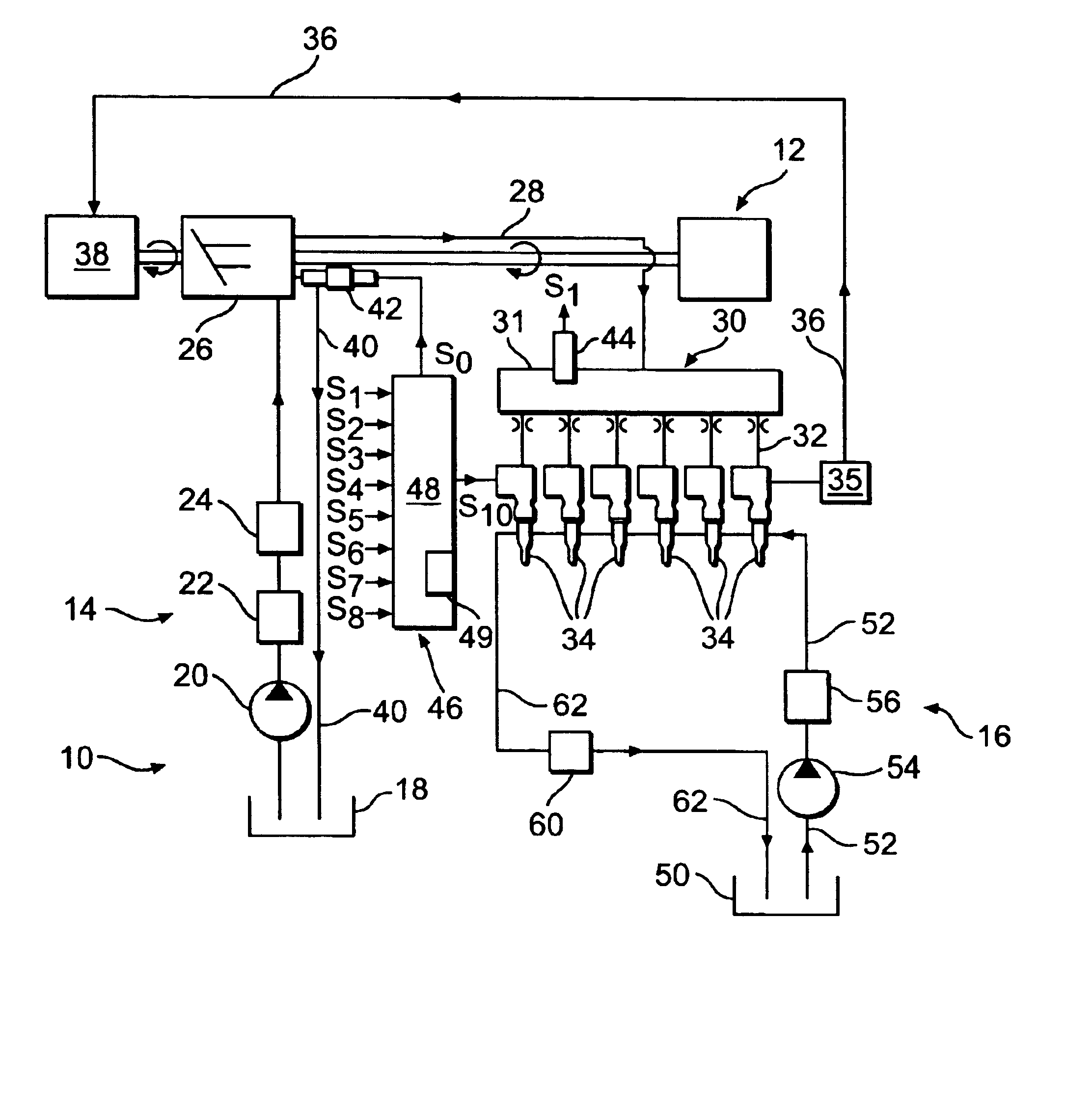
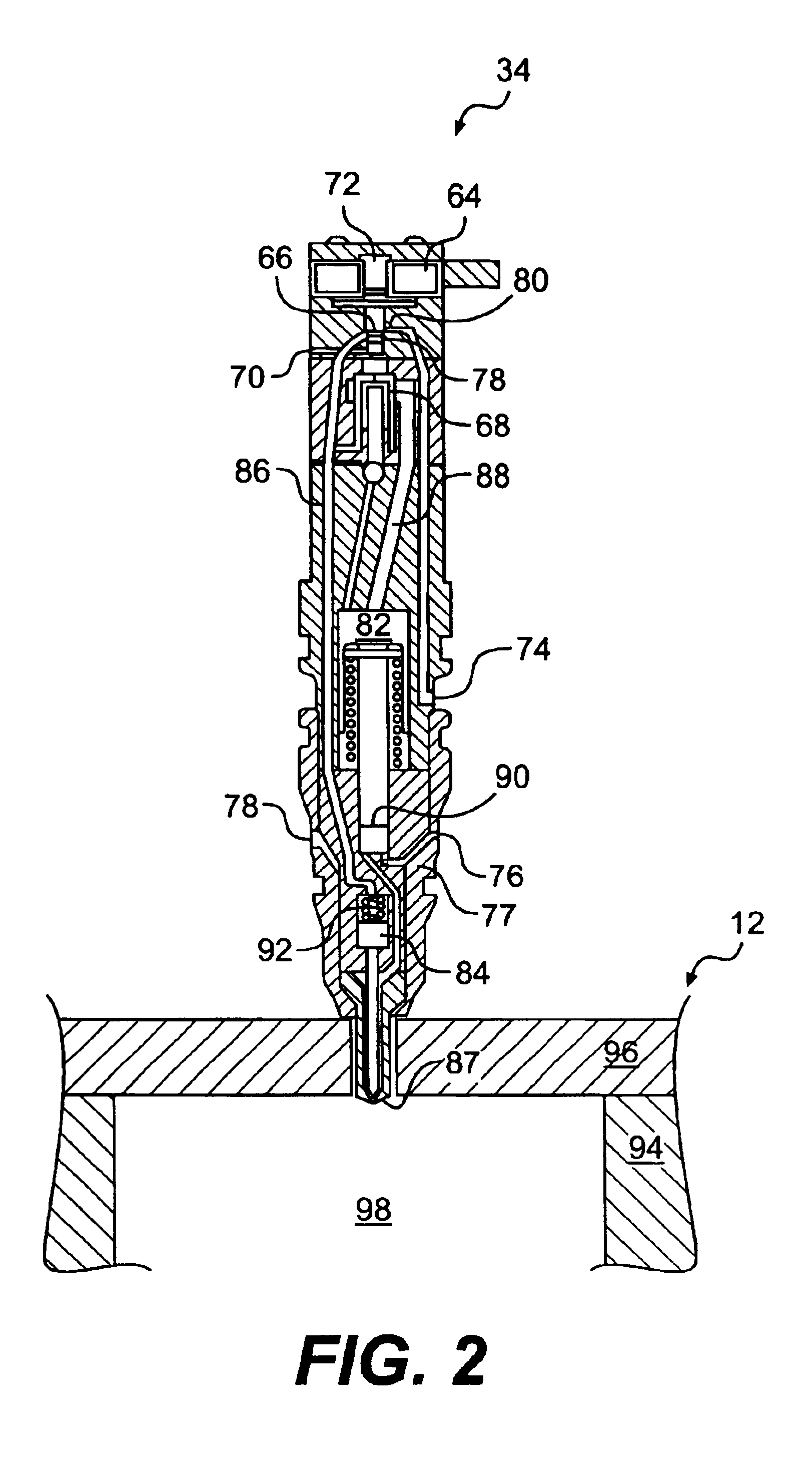
Reference will now be made in detail to exemplary embodiments of the invention, which are illustrated in the accompanying drawings. Wherever possible, the same reference numbers will be used throughout the drawings to refer to the same or like parts.

An exemplary embodiment of a fuel injection control system is illustrated in FIG. 1 and is designated generally by reference number 10. The illustrated fuel injection control system 10 is adapted for a direct injection diesel cycle internal combustion engine 12. It should be understood, however, that fuel injection control system 10 may be used with other types of internal combustion engines, such as, for example, gasoline or natural gas engines.

Fuel injection control system 10 includes an operating fluid supply system 14. Operating fluid supply system 14 includes a tank 18 configured to hold a supply of operating fluid, which may be, for example, hydraulic oil or fuel. A first source of pressurized fluid 20, which may be, for example, a...


PUM


Abstract

A method of estimating an injection delay of a fuel injector. A baseline injection delay curve representing an injection delay for a predetermined type of fuel injector is established for a range of rail pressures. At least one test rail pressure for the predetermined type of fuel injector is identified based on the baseline injection delay curve. An injection delay of a selected fuel injector of the predetermined type is measured at the at least one test rail pressure. The injection delay of the selected fuel injector is estimated based on the baseline injection delay curve and the measured injection delay of the selected fuel injector at the identified test rail pressure.

Description

TECHNICAL FIELDThe present disclosure is directed to a method and system for controlling a fuel injector, and, more particularly, the present disclosure is directed to a method of estimating a performance characteristic of a fuel injector.BACKGROUNDA fuel injector is commonly used to deliver fuel to a combustion chamber in an internal combustion engine. The fuel injector may deliver a certain quantity of fuel, which may be, for example, diesel, gasoline, or natural gas, to the combustion chambers in the engine at a certain time in the operating cycle of the engine. The amount of fuel delivered to the combustion chamber may depend on the operating conditions of the engine such as, for example, the engine speed and the engine load.Precisely controlling the quantity and timing of the fuel delivered to each combustion chamber in the engine may lead to an increase in engine efficiency and / or a reduction in the generation of undesirable emissions. To improve control over the quantity and ...

Claims


Application Information

Patent Timeline
IPC IPC(8): F02M65/00F02M57/00F02D41/00F02M57/02F02D41/24F02D41/38F02D41/40
CPCF02D41/2441F02D41/2467F02D41/38F02M57/025F02M65/00F02D41/401Y02T10/44F02D2200/0602Y02T10/40
Inventor JALIWALA, SALIM A.LUKICH, MICHAEL S.SCHURICHT, SCOTT R.SANKAR, RAMMOHAN
Owner CATERPILLAR INC
Why Eureka
Try Eureka