Dynamically reconfigurable precision signal delay test system for automatic test equipment

a test system and signal delay technology, applied in the direction of resistance/reactance/impedence, testing circuits, instruments, etc., can solve the problems of high requirements for testing a large number of different path delays and the complexity of test systems used for functional testing, and achieve the effect of efficient memory us

Inactive Publication Date: 2005-04-12
ADVANTEST CORP
View PDF5 Cites 34 Cited by
  • Summary
  • Abstract
  • Description
  • Claims
  • Application Information

AI Technical Summary

Benefits of technology

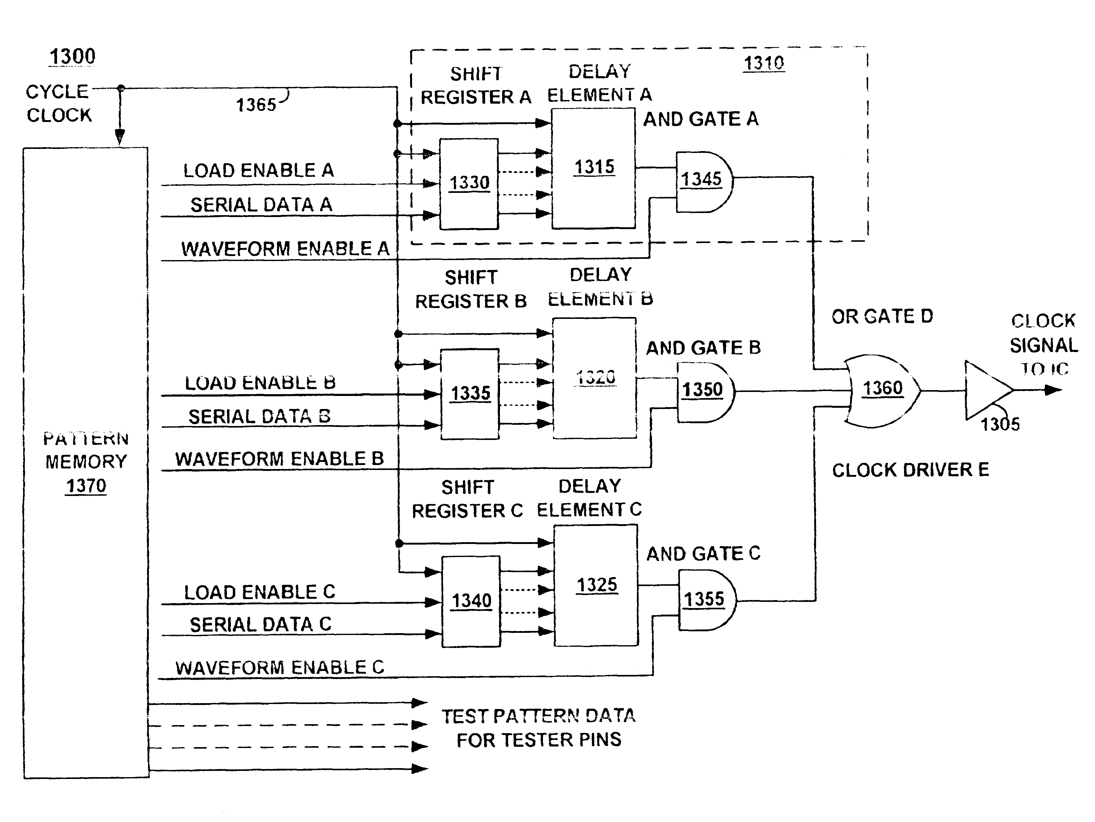
Accordingly, what is needed is an improved ATE system that provides more efficient generation of waveforms for performing delay testing with scan based testing. More specifically, what is needed is an ATE system that allows the efficient use of memory while allowing for a wide range of timing waveform variations. The embodiments of the present invention provide such advantages. These and other aspects of the present invention not recited above will become clear within the descriptions of the present invention presented below.

Problems solved by technology

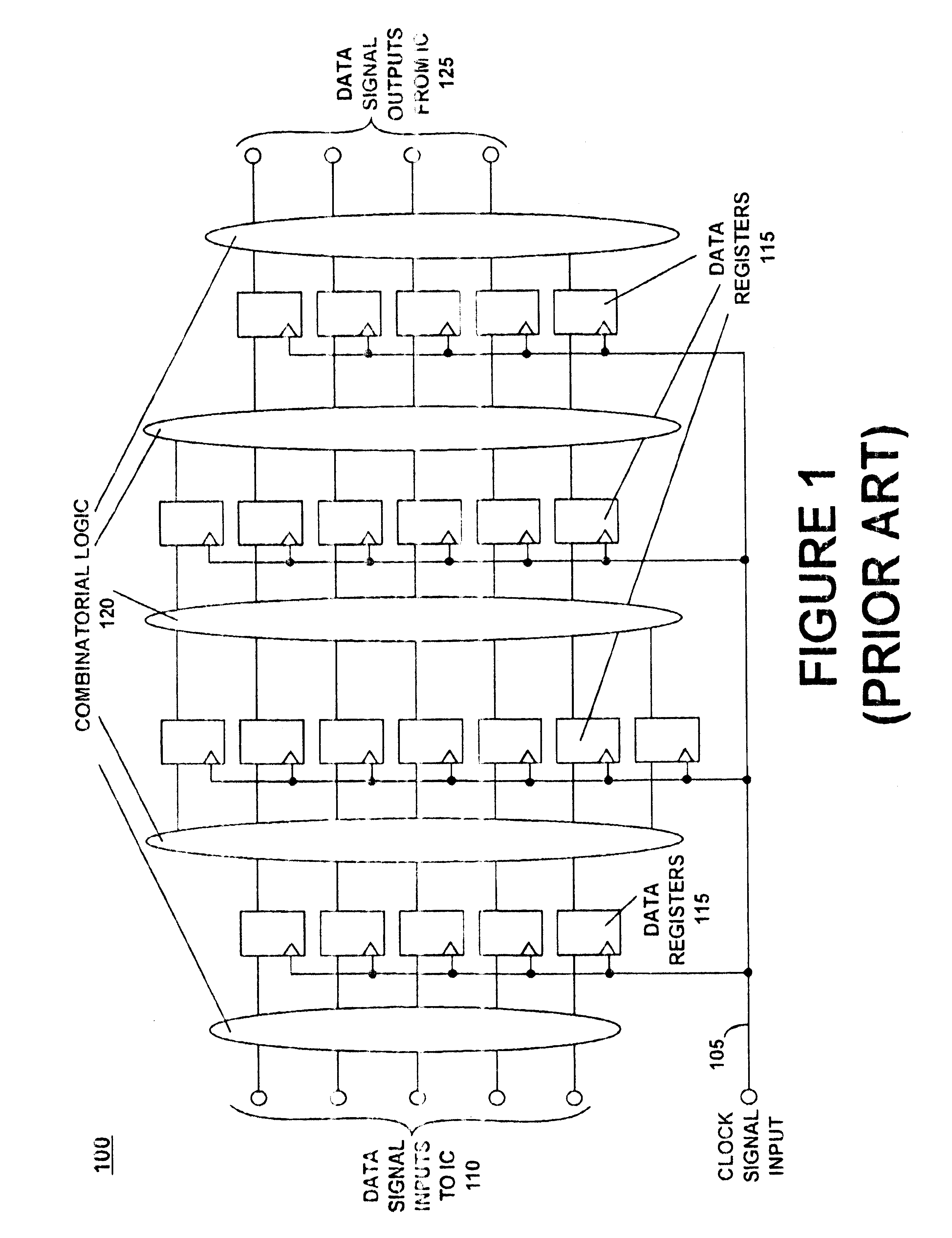
Since an IC may have several hundred input / output signals, and potentially require more complex timing than described above, the complexity of test systems used for functional testing can be very high.
One of the potential problems that can be encountered in the previous technique is the inability to create a pattern state that can cause a transition on a particular path or node.
However, requirements for testing a high number of different path delays (tcycle, Prior Art FIGS.

Method used


Image

  • Dynamically reconfigurable precision signal delay test system for automatic test equipment
  • Dynamically reconfigurable precision signal delay test system for automatic test equipment
  • Dynamically reconfigurable precision signal delay test system for automatic test equipment

Examples


Embodiment Construction

Reference will now be made in detail to the embodiments of the invention, dynamically reconfigurable precision signal delay test systems for Automatic Test Equipment (ATE), examples of which are illustrated in the accompanying drawings. While the invention will be described in conjunction with the preferred embodiments, it will be understood that they are not intended to limit the invention to these embodiments. The invention is intended to cover alternatives, modifications and equivalents, which may be included within the spirit and scope of the invention as defined by the appended claims. Furthermore, in the following detailed description of the present invention, numerous specific details are set forth in order to provide a thorough understanding of the present invention. However, it will be obvious to one of ordinary skill in the art that the present invention may be practiced without these specific details. In other instances, well known methods, procedures, components, and cir...


PUM


Abstract

A programmable time event and waveform generator for the application of precise timing patterns to a logic circuit and the capture of response data from the logic circuit. The time event and waveform generator comprises a programmable delay element that is programmed with values stored in pattern memory. For scan based testing, the time event and waveform generator is programmed between test pattern scan sequences by serial loading from the test pattern memory. The generator may be used to generate precise signal transitions to input pins of a circuit under test, and to capture at precise times the signal states from the output pins of a circuit under test. The data for programming the delay element is accessed from test pattern memory.

Description

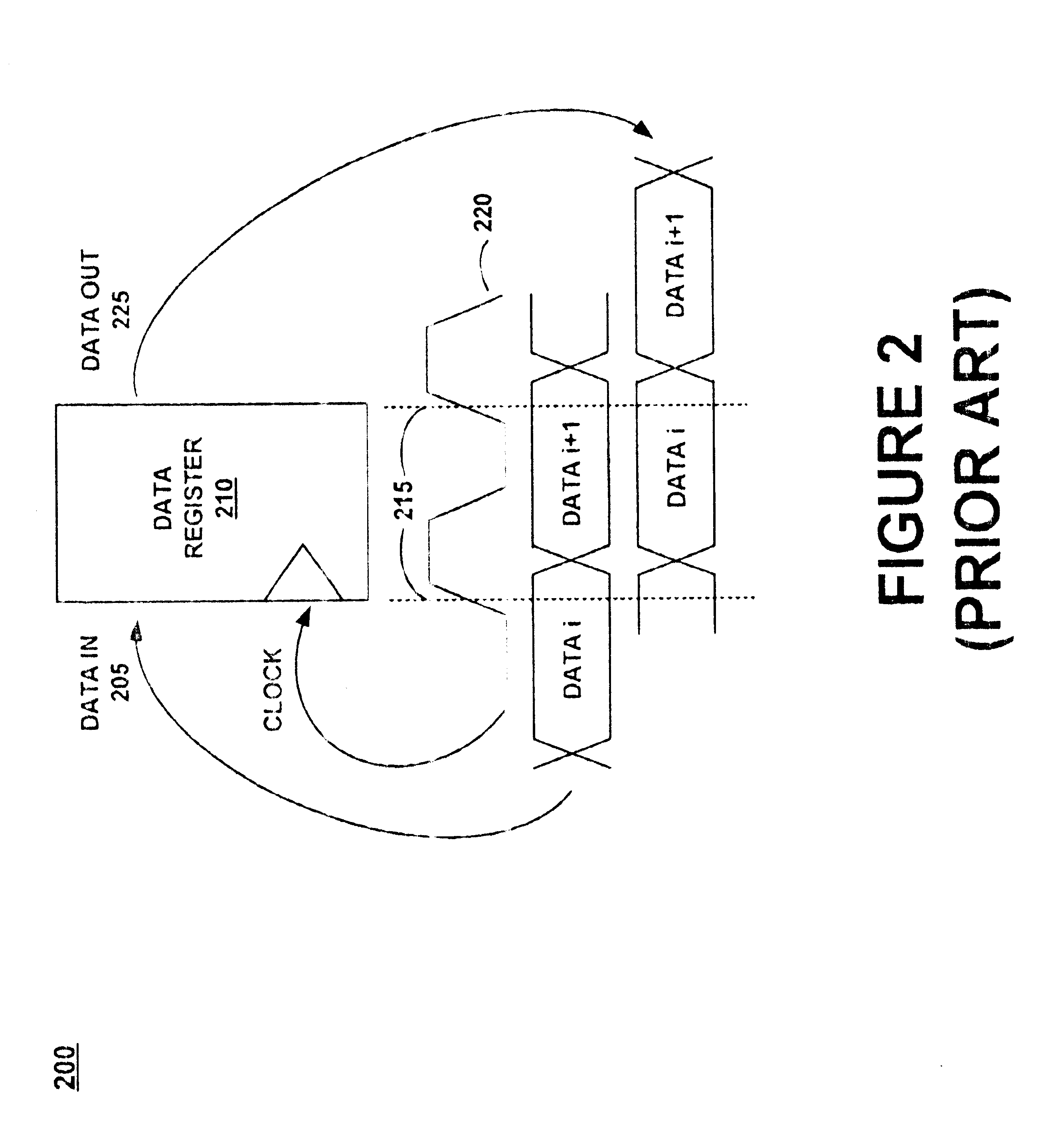
FIELD OF THE INVENTIONThe present invention relates to Automatic Test Equipment (ATE) used to test digital semiconductor integrated circuits (IC's). More specifically, the invention is directed to systems for performing precision digital signal delay testing on ICs that incorporate Design For Testability (DFT).BACKGROUND ARTATE for digital integrated circuits are required to provide digital stimulus to the integrated circuit (IC) and to measure the resultant digital response from the IC. One goal of this testing is to verify that there are no defects present in the IC that could affect its ability to perform its intended function. A second objective of testing is to verify that the IC will operate under its specified timing conditions. That is, verify that an IC not only performs the correct function, but performs it fast enough to meet its specification.Prior Art FIG. 1 depicts a diagram 100 of a simplified synchronous digital IC. The IC structure comprises a clock input 105, digit...

Claims


Application Information

Patent Timeline
Patent Type & Authority Patents(United States)
IPC IPC(8): G01R31/28G01R31/3185
CPCG01R31/318552G01R31/318547
Inventor BURLISON, PHILLIP D.DOEGE, JASON E.
Owner ADVANTEST CORP
Why Eureka
Try Eureka