Evaporative fuel processing system

a technology of evaporative fuel and processing system, which is applied in the direction of combustion air/fuel air treatment, electric control, instruments, etc., can solve the problems of insufficient purging of evaporative fuel stored in the canister, inability to obtain, and small fuel amount supplied

Inactive Publication Date: 2005-04-19
HONDA MOTOR CO LTD
View PDF8 Cites 37 Cited by
  • Summary
  • Abstract
  • Description
  • Claims
  • Application Information

AI Technical Summary

Benefits of technology

[0008]One embodiment of the present invention provides an evaporative fuel processing system which can purge a comparatively large amount of evaporative fuel to the intake system of the engine during the turbocharger operation.
[0009]A second embodiment of the present invention provides an evaporative fuel processing system which can prevent ignition of the air-fuel mixture containing evaporative fuel, when purging a comparatively large amount of evaporative fuel to the intake system during the turbocharger operation.
[0011]With this configuration, when the air pressurized by the turbocharger is discharged from the nozzle of the jet pump, a flow is generated by the discharging air flow, due to the viscosity of the discharging air, and this flow generates a negative pressure. Accordingly, without the pressurized air flowing upstream of the second purge passage, the air-fuel mixture containing evaporative fuel is attracted from upstream of the second purge passage, and emitted from the jet pump, thereby supplying the air-fuel mixture upstream of the turbocharger in the intake pipe. Consequently, the evaporative fuel can be purged during turbocharger operation from the canister to the intake pipe, thereby preventing the evaporative fuel from accumulating in the canister.
[0015]With this configuration, the intake evaporative-fuel concentration, which is an evaporative-fuel concentration upstream of the turbocharger, is calculated, and the control for decreasing the opening of the purge control valve is performed when the intake evaporative-fuel concentration exceeds the predetermined concentration during turbocharger operation. Therefore, the intake evaporative-fuel concentration can be controlled to maintain a value below the predetermined concentration, which makes it possible to prevent the air-fuel mixture containing the evaporative fuel from igniting.

Problems solved by technology

Therefore, the evaporative fuel stored in the canister cannot be sufficiently purged to the intake pipe only by a usual purge passage which supplies the evaporative fuel to a portion downstream of the throttle valve.
However, it is confirmed by experiments that a sufficient negative pressure cannot be obtained only by disposing the venturi part in the connection passage, so that the evaporative fuel is hardly supplied to the intake pipe, or the supplied fuel amount is a very small even if the evaporative fuel can be supplied to the intake pipe.
Further, if the evaporative fuel is supplied to the upstream side of the turbocharger, the intake air and the evaporative fuel is mixed and an evaporative-fuel concentration in the air-fuel mixture may reach a flammability limit.
When the evaporative-fuel concentration reaches the flammability limit, there is a possibility that the air-fuel mixture may actually ignite with the heat generated in a compressor and a turbine of the turbocharger.

Method used


Image

  • Evaporative fuel processing system
  • Evaporative fuel processing system
  • Evaporative fuel processing system

Examples


Embodiment Construction

[0024]Preferred embodiments of the present invention will now be described with reference to the drawings.

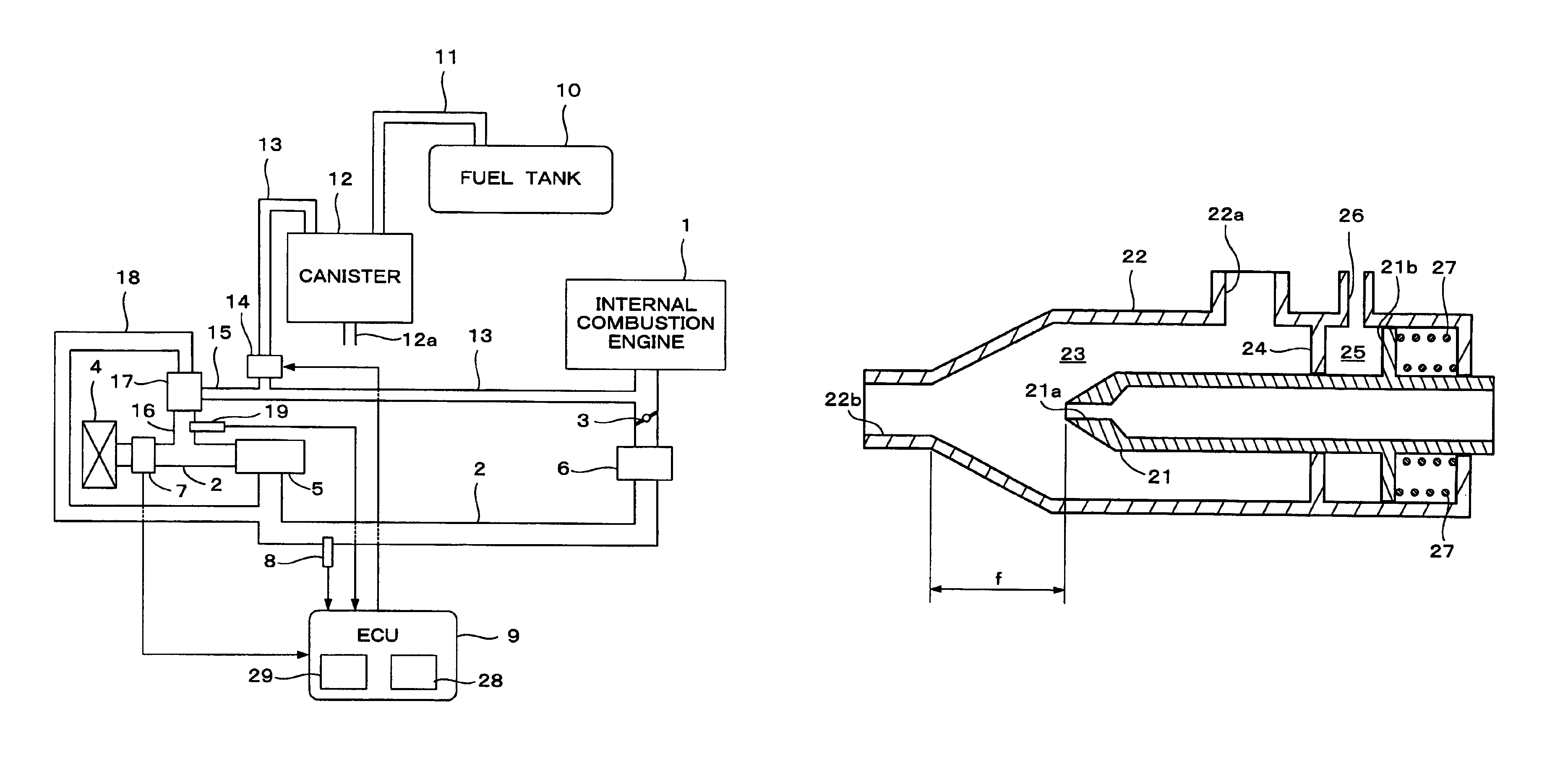
[0025]FIG. 1 is a schematic diagram showing a configuration of an evaporative fuel processing system according to one embodiment of the present invention, and an intake system of an internal combustion engine. An internal combustion engine (hereinafter “engine”) 1 has an intake pipe 2, and the intake pipe 2 is provided with an air cleaner 4, a turbocharger 5, an intercooler 6, and a throttle valve 3 in this order an upstream direction. The turbocharger 5 has a turbine rotationally driven by the exhaust gas energy, and a compressor which is rotated by the turbine and pressurizes intake air. The turbocharger 5 discharges pressurized air downstream in the intake pipe 2.

[0026]A fuel tank 10 is connected to a canister 12 through a charge passage 11, and the canister 12 is connected through a first purge passage 13 to a portion of the system downstream of the throttle valve 3 in the i...


PUM


Abstract

An evaporative fuel processing system for processing evaporative fuel generated a fuel tank. A canister temporarily stores evaporative fuel generated in the fuel tank. A charge passage connects the fuel tank and the canister. A first purge passage connects the canister and an intake pipe of an internal combustion engine having a turbocharger. A purge control valve is provided in the first purge passage for adjusting a flow rate of gases flowing through the first purge passage. A second purge passage connects a downstream side of the purge control valve of the first purge passage and an upstream side of the turbocharger of the intake pipe. A jet pump is mounted on the second purge passage. A pressurized air supply passage supplies air pressurized by the turbocharger to the jet pump. The jet pump includes a nozzle for discharging the pressurized air supplied through the pressurized air supply passage.

Description

BACKGROUND OF THE INVENTION[0001]1. Field of the Invention[0002]The present invention relates to an evaporative fuel processing system which temporarily stores evaporative fuel generated in a fuel tank, and timely supplies the evaporative fuel to an intake system of an internal combustion engine, and particularly to an evaporative fuel processing system which supplies the evaporative fuel to an internal combustion engine having a turbocharger.[0003]2. Description of the Related Art[0004]In Japanese Utility Model Laid Open Sho 63-162965, an evaporative fuel processing system which supplies evaporative fuel to an intake pipe of an internal combustion engine having a turbocharger is disclosed. In the internal combustion engine having a turbocharger, the intake pressure at a portion downstream of the turbocharger becomes higher than the atmospheric pressure when the turbocharger is operating. Therefore, the evaporative fuel stored in the canister cannot be sufficiently purged to the int...

Claims


Application Information

Patent Timeline
Patent Type & Authority Patents(United States)
IPC IPC(8): F02D41/00F02M25/08
CPCF02M25/08F02D41/0045F02D41/0032F02D41/187
Inventor YOSHIKI, KOICHIIMAMURA, KAZUHIKOKOHNO, RYUJISHIKAMA, MAHITOTERAKADO, TOSHIICHIMAEDA, KENICHIWAKUI, MASAYUKI
Owner HONDA MOTOR CO LTD
Why Eureka
Try Eureka