Extensible linear light emitting diode illumination source

a light emitting diode and linear technology, applied in the field of linear light sources, can solve the problems of false identification of defects, limited brightness of existing illumination arrays, and insufficient illumination, and achieve the effects of high reliability, maximum brightness, and uniform illumination

Inactive Publication Date: 2005-04-19
WINTRISS ENG
View PDF12 Cites 131 Cited by
  • Summary
  • Abstract
  • Description
  • Claims
  • Application Information

AI Technical Summary

Benefits of technology

[0006]It is an advantage of the present invention to provide an illumination source that utilizes an illumination elements, e.g, light emitting diodes, to provide maximum brightness, long life, and diffuse or focused light of various wavelengths.
[0007]It is a further advantage to provide an illumination source that is extensible to any length while providing uniformity of illumination.
[0008]If is another advantage to provide an illumination source that individually groups LEDs to avoid catastrophic failure of the entire linear LED array.
[0009]Another advantage of the present invention is to provide an illumination source that has a power distribution system that provides equal power to each LED of the linear LED array.
[0010]Yet another advantage is to provide an environmentally sealed illumination source having structural supports which act as heat sinks, include cooling channels for forced air and other cooling means, and provide flexible mounting provisions.
[0011]The exemplary embodiment of the present invention is a compact, energy-efficient extensible illumination source that utilizes light emitting diodes (LEDs) to provide the advantages of brightness and high reliability. The high reliability of the LEDs provides trouble-free operation over a long hour lifetime. The illumination source of the exemplary embodiment includes LED printed wire board segments that may be configured to form a light line of any length. The segments are mounted on a inner mounting base which also serves as a first stage heat sink for the LEDs. Linear mirrors are mounted on the inner mounting base with the LEDs running lengthwise between the mirrors. The mirrors reflect and focus the radiant energy from the LEDs onto the target to produce a uniform linear illumination pattern. A window is mounted in the illumination source above the LEDs and mirrors to provide mechanical protection for the LEDs. The window may be used for diffusing or filtering light from the LEDs.

Problems solved by technology

Although the analysis may correct for minor lighting variations, dark spots caused by defective or inconsistent lighting may result in a false identifications of defects.
However, these LED linear arrays often are of a fixed length that are not sufficiently long to illuminate a target width.
Linear arrays that are extensible use modules that, when connected together, result in gaps between the modules so that the illumination is not uniform.
In addition, the brightness of the existing illumination arrays are limited, and the focus of the light is not controllable.
Typical prior art illumination sources do not provide sufficient provisions for heat flow away from the illumination source.
In addition, these products do not have power supply distribution provisions, and are not sealed for use in extreme environments.

Method used


Image

  • Extensible linear light emitting diode illumination source
  • Extensible linear light emitting diode illumination source
  • Extensible linear light emitting diode illumination source

Examples


Embodiment Construction

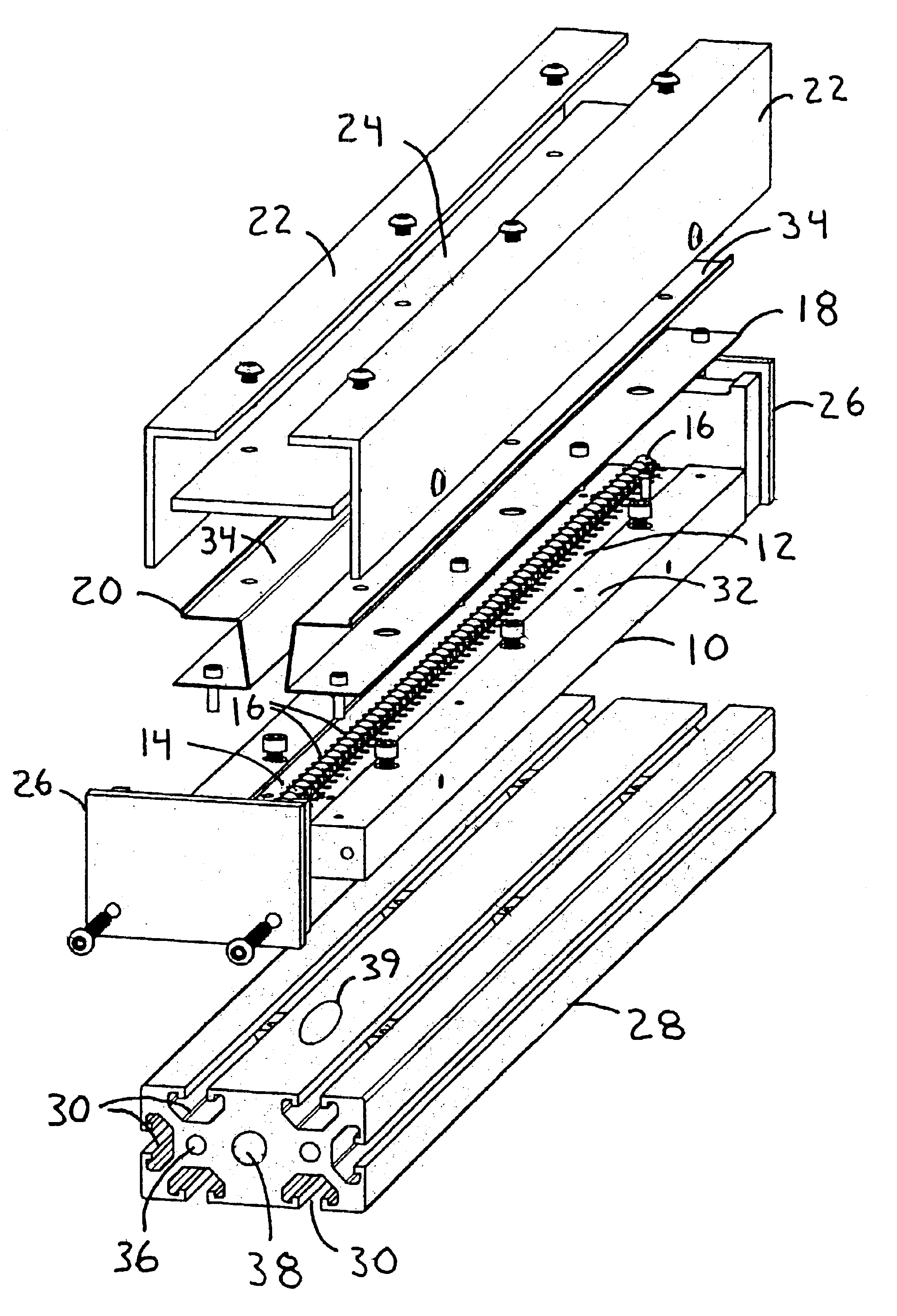
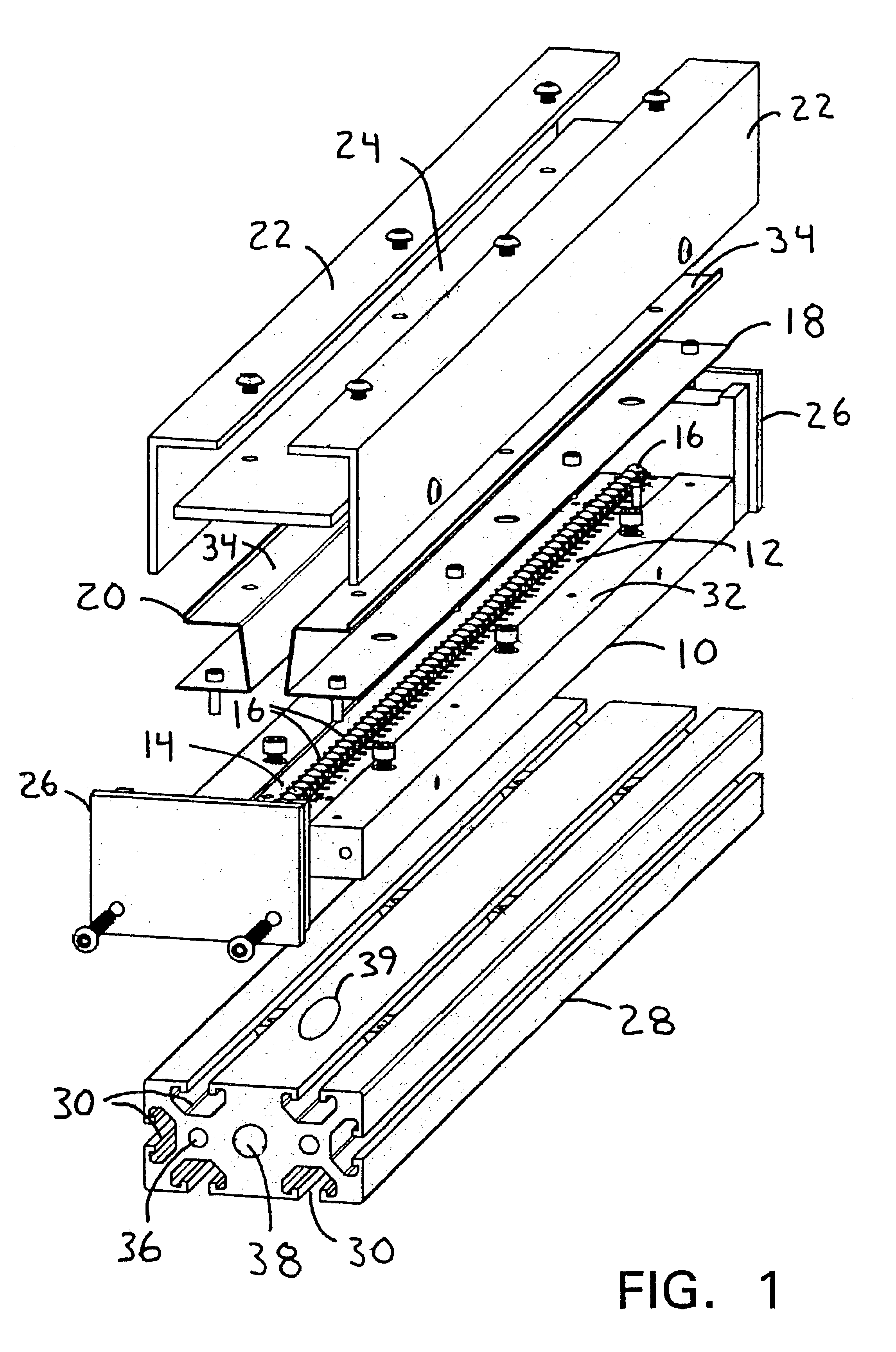
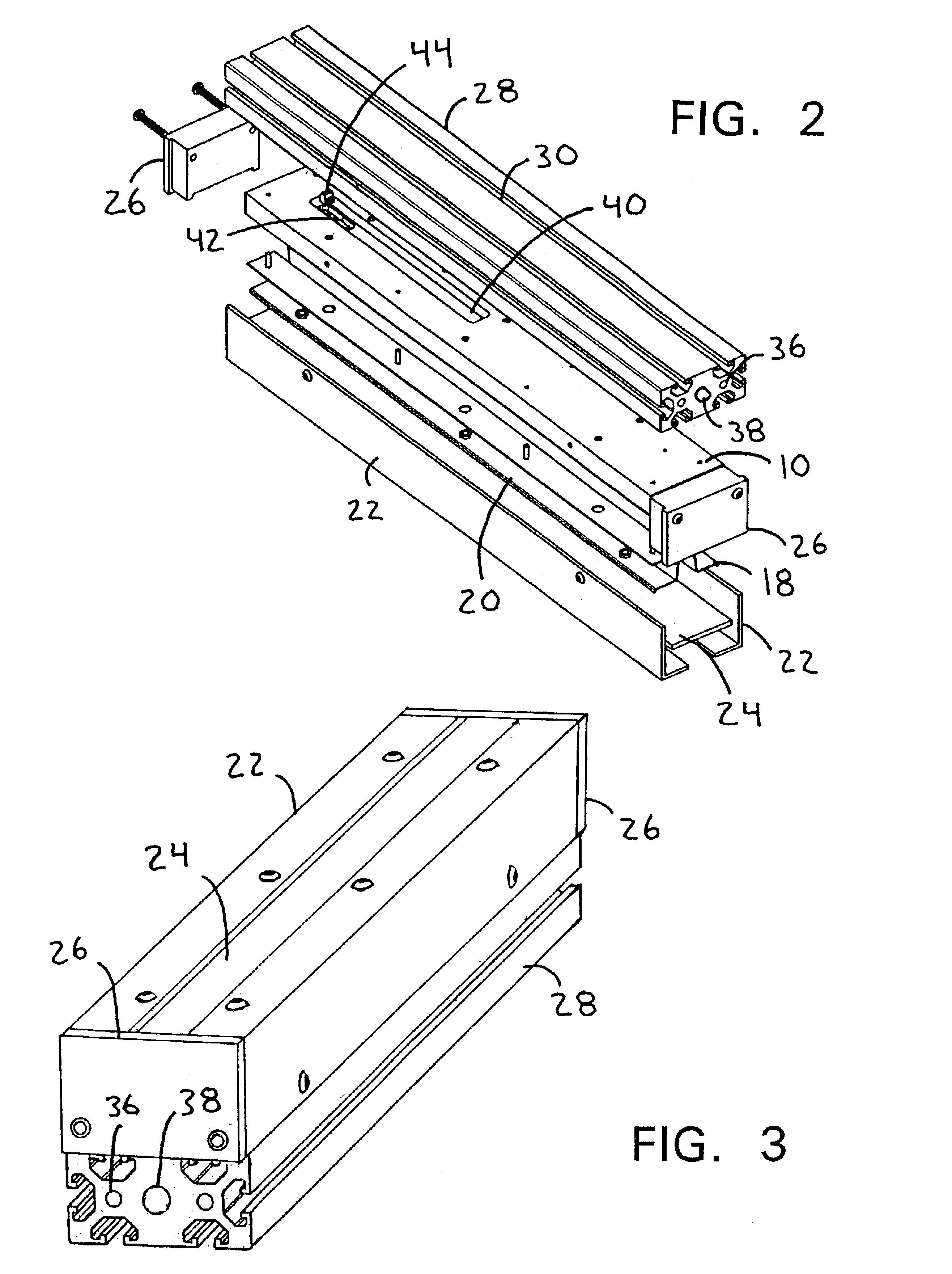
[0029]FIG. 1 illustrates an exploded view of an assembly of an extensible linear light emitting diode illumination source of a preferred embodiment of the present invention, while FIG. 3 illustrates the assembled illumination source and FIG. 11 illustrates a web inspection system utilizing the extensible linear light emitting diode illumination source 2. The illumination source 2 includes an inner printed wire board (PWB) mounting base 10 attached to a base 28. Right and left mirrored window supports 18, 20 are mounted to a top surface 32 of the PWB mounting base 10. A window 24 is mounted to top surfaces 34 of the window supports 18, 20. The PWB mounting base 10, the mirrored window supports 18, 20, and the window 24 are enclosed by brackets 22 and end caps 26. The brackets 22, end caps 26, base 28 and window 24 create an environmentally sealed assembly 2.

[0030]Continuing with FIG. 1, the illumination source 2 includes light emitting diodes (LEDs) 16, which are positioned along an ...


PUM

PropertyMeasurementUnit
inside angleaaaaaaaaaa
lengthaaaaaaaaaa
widthaaaaaaaaaa

Abstract

A compact, energy-efficient extensible illumination source combines the reliability advantages of light emitting diodes (LEDs) with the brightness of conventional lighting. High reliability of the LEDs provides trouble-free operation over a long hour lifetime. This high-output light source can be used in direct lighting applications or for backlighting for translucent materials. The illumination source includes LED printed wire board segments that may be configured to form a light line of any length. The segments are mounted on a inner mounting base which also serves as a first stage heat sink for the LEDs. The illumination source includes a linear mirror for reflecting radiant energy away from the LEDs to produce a uniform linear illumination pattern. A window provides mechanical protection for the LEDs and may be used for diffusing or filtering light from the LEDs. An integral base in contact with the inner mounting base also serves as a heat sink and provides structural support for the illumination source. The integral base further includes channels and cavities for cooling the illumination source and for housing power cables.

Description

RELATED APPLICATIONS[0001]This application claims the benefit of priority under 35 U.S.C. 119(e) to provisional U.S. patent application Ser. No. 60 / 366,066, filed Mar. 18, 2002 which is incorporated herein by reference in its entirety.FIELD OF THE INVENTION[0002]This invention relates generally to linear light sources, and more specifically to an assembly of high-intensity light emitting diodes in a linear, modular form such that the illumination line can be extended indefinitely.BACKGROUND OF THE INVENTION[0003]Linear light arrays are desirable for use when an specific long, narrow target area must be illuminated. One such use is for illumination of a continuous web in a web manufacturing inspection system. A web is any material which is manufactured in a single continuous sheet, such as paper and cloth. The web typically passes through a web inspection station that analyzes the web for defects. Cameras are positioned along the width of a web, with each camera taking images of a sp...

Claims


Application Information

Patent Timeline
Patent Type & Authority Patents(United States)
IPC IPC(8): F21V29/00F21S2/00F21S4/00G01N21/88F21V29/02F21V15/015F21V15/01F21V15/00
CPCF21S4/008F21V29/004F21V29/74G01N21/8806F21V15/013F21V15/015F21V29/02F21W2131/403F21Y2101/02Y10S362/80F21V29/30F21S4/28F21Y2115/10F21V29/70
Inventor KIRALY, CHRISHENKE, GENE
Owner WINTRISS ENG
Why Eureka
Try Eureka