Reduction in mineral salt deposition

a technology of mineral salt and reduction, applied in the direction of crystal growth process, magnesium halide, complexing/solubilising chemical treatment, etc., can solve the problems of pipe blockage, increase pressure loss, pipe flow rate reduction, etc., and achieve the effect of economic energy on a large scal

Inactive Publication Date: 2005-04-19
ASYMPTOTE
View PDF15 Cites 12 Cited by
  • Summary
  • Abstract
  • Description
  • Claims
  • Application Information

AI Technical Summary

Benefits of technology

[0011]It has now been found that scale control is particularly effective where the Mean particle size of the seed crystals is less than 2.5 microns (μm). Such seed crystals can be prepared using a process which is economic in energy on a large scale.

Problems solved by technology

If scale is allowed to build up in a system, it causes increased pressure losses, reduction in flow rate in pipes or heat exchange capacity and ultimately pipe blockage.
In the production of hydrocarbons from subterranean formations the deposition of scale such as barium or strontium sulphate, calcium carbonate, calcium sulphate or calcium fluoride on surfaces and production equipment is a major production problem.
Scale build-up reduces well productivity and shortens the lifetime of production equipment.
But these are expensive and contaminate the water.
As the fluid enters the crystal generator there is a sudden pressure drop accompanied by a sudden increase in flow velocity and a high degree of turbulence.
Since this method is said to be only feasible for small systems, its application is limited.

Method used


Image

  • Reduction in mineral salt deposition
  • Reduction in mineral salt deposition
  • Reduction in mineral salt deposition

Examples


example 1

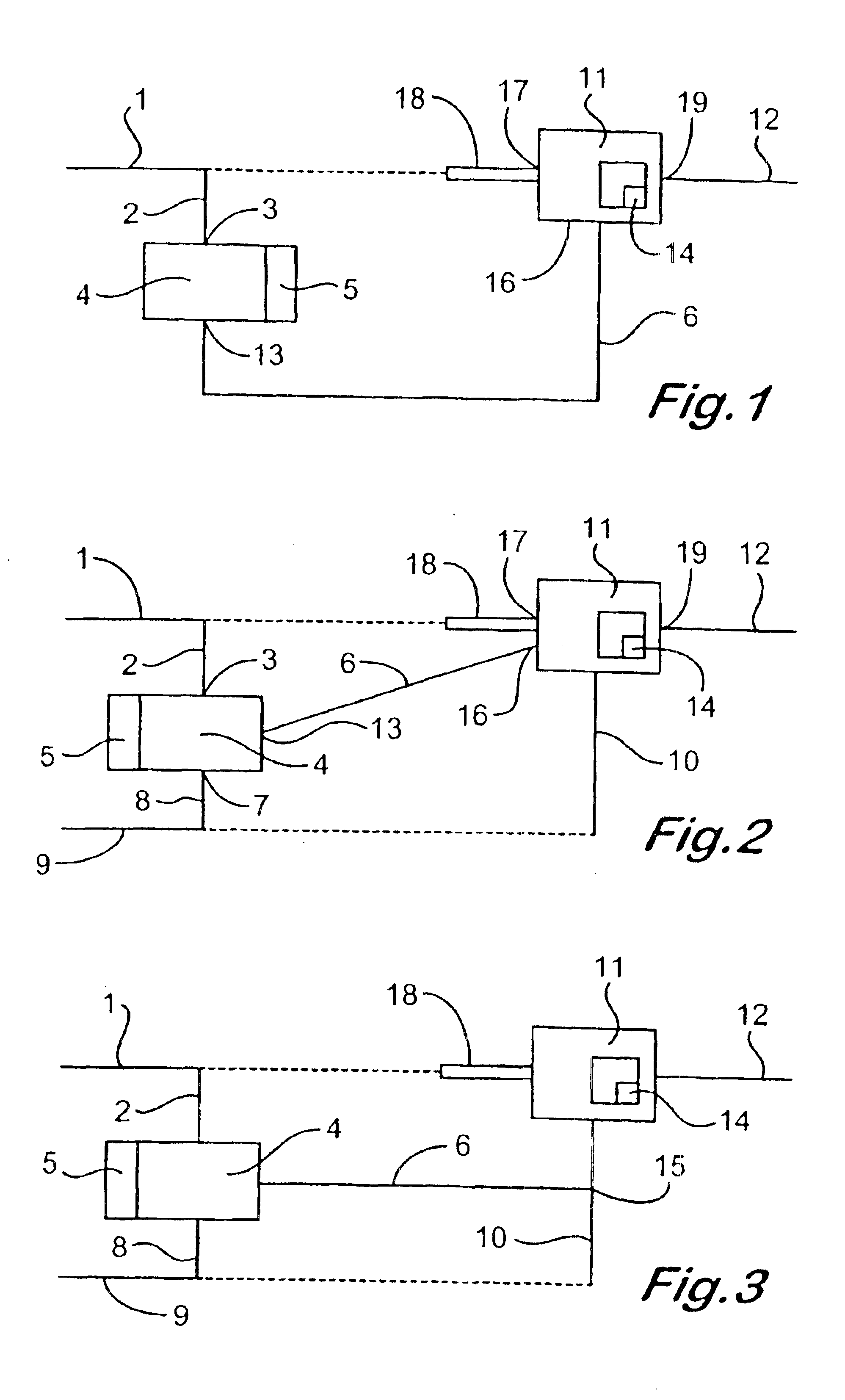
[0093]The apparatus as illustrated in FIG. 2 was used with lines 1 and 18 joined and 9 and 10 joined, with flow rates of 0.05 ml / min of Formation Water (FW) in line 2, 4.95 ml / min of FW entering chamber 11 from line 18, 0.05 ml / min of Sea Water (SW) in line 8 and 4.95 ml / min of SW entering chamber 11 in line 10, and 0.1 ml / min of seed crystal suspension entering chamber 11 in line 6. A coil of stainless steel tube one sixteenth of an inch (1.6 mm) internal diameter was present in line 6 and another in line 12, both for liquid hold up purposes and a blockable tube downstream of the coil in line 12 was present to determine blocking pressures or deposition rates. The lines 1, 2, 6, 8, 10 were all (one eighth inch (3.2 mm) ID tube.

[0094]The Formation water in lines 2 and 10 contained:

[0095]NaCl (64.24 g / L), NaHCO3 (2.82 g / L), CaCl2.2H2O(2.35 g / L); KCl (2.25 g / L), BaCl2.2H2O(1.39 g / L), MgCl2.6H2O(0.88 g / L), SrCl2.6H2O (0.24 g / L) in 1 liter water and pH adjusted to 4.5 by dropwise additio...

example 2

[0104]The process of Example 1 with ultrasound was repeated with a lower ultrasound power input namely 1600 J / cm3. Similar results to those in Example 1 were obtained for the particle (crystal) size parameters.

example 3

[0105]The process of Example 1 was repeated but with the apparatus of FIG. 3, with separate feed lines of formation water in lines 1 and 18 to chambers 4 and 11, and with separate feed lines of sea water in lines 8 and 10. In this way the effect of different relative flow rates of seed slurry in line 6 and formation water into chamber 11 was changed. The results were as follows. Flow rates in lines 1 and 6 were 2 l / min., and 8.7 l / min in each of the lines for formation and sea water into chamber 11. These give a percentage of seed slurry to total liquid in chamber 11 of 10% (by weight). Residence times were 3.1 sec from chamber 4 to location 15, 3.5 sec from, location 15 to chamber 11, and 3.8 sec from chamber 11 to the blockable tube. No blocking occurred. With the latter two residence times reduced to 2.1 sec and 1.2 sec respectively (and sea water and formation water flow rates of 8.5 l / min each giving a 11% seed percentage) blocking occurred.

[0106]With different flow rates (name...


PUM

PropertyMeasurementUnit
mean particle sizeaaaaaaaaaa
frequencyaaaaaaaaaa
frequencyaaaaaaaaaa

Abstract

A composition for reducing deposition of a mineral salt from an aqueous supersaturated solution onto a solid surface in contact with the aqueous supersaturated solution which composition comprises a dispersion of either (i) seed crystals of the mineral salt in an aqueous solution of the mineral salt or (ii) seed crystals of a salt isomorphous with the mineral salt in an aqueous solution of the isomorphous salt wherein the dispersed seed crystals are of Mean particle size of less than 2.5 microns.

Description

[0001]This application is a continuation of Application No. PCT / GB00 / 02368, filed 19 Jun. 2000, the entire content of which is hereby incorporated by reference in this application.[0002]This invention relates to methods of reducing deposition of mineral salts, in particular, from aqueous supersaturated solutions, and especially concerns reducing scaling.BACKGROUND OF THE INVENTION[0003]Water often contains inorganic salts, in particular those of calcium and / or barium which may be of sparing solubility in water and tend to deposit on the inside walls of pipes, and in valves and tanks and on heat exchangers as scale. If scale is allowed to build up in a system, it causes increased pressure losses, reduction in flow rate in pipes or heat exchange capacity and ultimately pipe blockage. Scaling of equipment may arise, for example, in the petrochemical industry, in power generation, and in paper pulp manufacture.[0004]In the production of hydrocarbons from subterranean formations the depo...

Claims


Application Information

Patent Timeline
Patent Type & Authority Patents(United States)
IPC IPC(8): B01D9/00C02F5/00C02F5/06C09K8/528C09K8/52C02F1/36C02F1/34C02F5/02B01D9/02
CPCB01D9/0036C02F5/06C09K8/528B01D9/005C02F1/36Y10S423/08
Inventor ACTON, ELIZABETHMORRIS, GEORGE JOHN
Owner ASYMPTOTE
Why Eureka
Try Eureka