
Method and device for preventing deposits in steam systems

a technology of steam system and preventing deposits, which is applied in the direction of cleaning using liquids, other chemical processes, and separation processes, etc., can solve the problems of high investment and operating costs, inability to use tried and tested chemical procedures for steam generators, and inability to prevent the deposition of contaminants. , to achieve the effect of preventing the deposition of contaminants

Inactive Publication Date: 2005-04-19
ALSTOM TECH LTD
View PDF8 Cites 14 Cited by
  • Summary
  • Abstract
  • Description
  • Claims
  • Application Information

AI Technical Summary

Benefits of technology

[0017]Accordingly, the invention is based on the object of providing a method for preventing the deposition of contaminants in steam systems in which the drawbacks of the prior art are avoided. In particular, it is intended to propose a method in which it is not necessary to use a high level of outlay to remove contaminants from the working medium used for the steam system to the highest possible degree or to prevent even the slightest possible contamination to this medium.
[0018]The inventive solution to the above object consists in metering an additive into steam systems of this type, which additive adheres to the steam-side surface of the steam system and has the effect of repelling moisture and contaminants. The essence of the invention therefore consists in using an additive to form a film on the components around which the steam flows, which film can effectively prevent deposits.
[0022]Additives usually have a limited service life. This applies in particular to organic substances, the service life of which is dependent on the temperature, on account of thermal decomposition. According to a further preferred embodiment of the method, the limited service life of the additives can advantageously be used to control the film height. However, for reasons of expediency, the additives should have a certain minimum service life, which is at least equal to, but preferably greater than the residence time during flow through the device for steam use. The constant, controlled decomposition of the additive therefore makes it possible to prevent the additive from accumulating within the steam system.
[0024]One embodiment of the invention is characterized in that the additive in the steam system forms a film of a defined height on components around which the steam flows, and in that this film height is controlled during operation by suitable metering of the additive, for example as a function of its service life, and in particular can preferably be set within a controlled range (redefined set range). Finally, the decomposition behavior of the additives also makes it possible to control the film thickness and its composition.

Problems solved by technology

Contaminants originating from steam-soluble substances in steam which is guided in this manner may lead to deposits forming on components around which the steam flows and therefore cause problems.
This results, not least, in numerous constraints being imposed on the steam generator technology used, for example with regard to component design (steam drying in drums and separators), the temperature control for the steam by injection of water or mixing of steam, chemical procedures, etc.
A drawback of these possibilities is that, for example, it is no longer possible to use tried-and-tested chemical procedures for steam generators.
Moreover, condensate-cleaning installations, in addition to a high outlay in terms of investment and operating costs, also entail additional risks.
Steam filters for separating out particles which are entrained in the steam also only have a limited effect.

Method used


Image

  • Method and device for preventing deposits in steam systems
  • Method and device for preventing deposits in steam systems
  • Method and device for preventing deposits in steam systems

Examples


Embodiment Construction

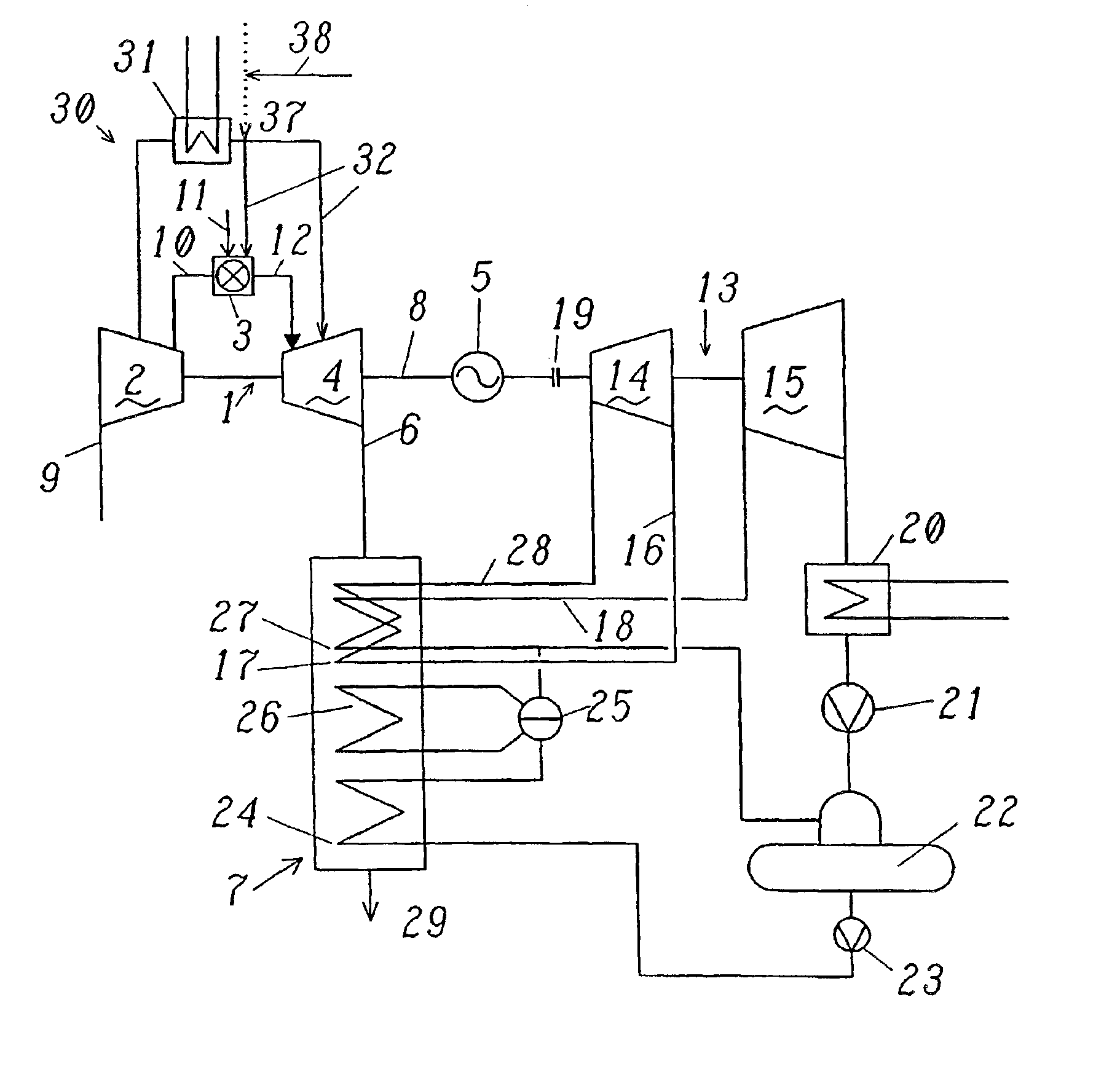
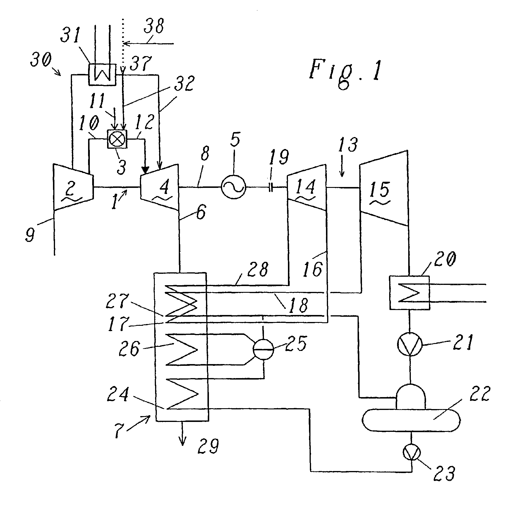
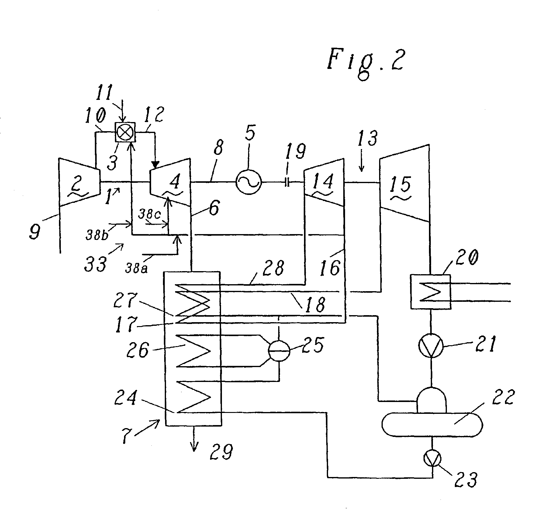
[0039]FIG. 1 shows, as an exemplary embodiment of the method according to the invention, a diagrammatic illustration of a combined-cycle power plant with a single-shaft installation. The water / steam cycle with heat recovery steam generator 7 and steam turbine installation 13 is designed, for example, as a single-pressure process with reheating 17.

[0040]In the text which follows, a combined-cycle power plant is understood as meaning the coupling of a gas process and a steam process in the form of a gas turbine installation and a steam turbine installation. The heat from the exhaust gases from the gas turbine of the gas turbine installation is used to generate steam in a heat recovery steam generator. The steam which is generated is utilized to generate current by means of the steam turbine installation.

[0041]As shown in FIG. 1, the combined-cycle power plant has a gas turbine installation 1, the exhaust gas 6 from which is fed to a heat recovery steam generator 7. The gas turbine ins...


PUM

PropertyMeasurementUnit
pressuresaaaaaaaaaa
Temperaturesaaaaaaaaaa
temperaturesaaaaaaaaaa

Abstract

The present invention relates to a method for preventing the deposition of contaminants in steam systems. In a method of this type, deposits are prevented in a simple and economic manner by metering an additive into the steam, which additive adheres to the steam-side surface of the steam system and has the effect of repelling moisture and contaminants.

Description

[0001]This application claims priority under 35 U.S.C. §§119 and / or 365 to Appln. No. 2001 1363 / 01 filed in Switzerland on Jul. 23, 2001; the entire content of which is hereby incorporated reference.FIELD OF THE INVENTION[0002]The present invention relates to a method for preventing the deposition of contaminants in steam systems. The invention also relates to a device for carrying out a method of this type.BACKGROUND OF THE INVENTION[0003]For reasons of efficiency, steam is increasingly being used as coolant for cooling components of energy machines, for example of a gas turbine installation, which are subject to high thermal loads. This steam can flow through the components which are to be cooled in an open, semi-open or closed system either in the form of steam or in the form of a steam / air mixture.[0004]In an open steam system, the steam is guided from a device for providing steam (heat recovery steam generator, steam turbine installation, auxiliary steam generator, etc.) to the...

Claims


Application Information

Patent Timeline
Patent Type & Authority Patents(United States)
IPC IPC(8): C02F5/12C02F5/00C02F5/02C02F5/10F01K21/00F01K21/06
CPCC02F5/025F01K21/06C02F5/12C02F2303/08
Inventor LIEBIG, ERHARDSVOBODA, ROBERT
Owner ALSTOM TECH LTD
Learn More