Vehicle AC generator with rectifier diode package disposed between cooling plates

a rectifier diode and rectifier technology, applied in the direction of rectification association, cooling/ventilation arrangement, electrical apparatus construction details, etc., can solve the problems of increasing the temperature of the rectifier unit b>12/b>b and the stator coil b>16/b>, and the diode having a larger heating value cannot be effectively cooled, so as to reduce the assembling man-hour, efficiently dissipate the heat produced in th

Inactive Publication Date: 2005-04-19
MITSUBISHI ELECTRIC CORP
View PDF16 Cites 16 Cited by
  • Summary
  • Abstract
  • Description
  • Claims
  • Application Information

AI Technical Summary

Benefits of technology

[0040]In order to solve the above-mentioned problems, it is an object of the present invention to provide a vehicle AC generator capable of restraining temperature increase in the of unidirectionally conducting elements of a rectifier unit by efficiently dissipating the heat produced in the elements and also capable of reducing the assembling man-hour by reducing the number of parts of the rectifier unit and as well of restraining the damage of the elements during the assembly of the rectifier unit, wherein the unidirectionally conducting elements for the positive- and negative-electrode sides are deposited in one piece interposing an AC input terminal therebetween and then metallic plate bases are joined to both ends of the deposited unidirectionally conducting elements, and thereby forming the rectifier unit.

Problems solved by technology

That is, the heat generated in the diodes 30a and 30b is dissipated independently from the cooling plates 31 and 32, respectively, so that when the heating value of the diode 30a is unbalanced with that of the diode 30b, there has been a problem that the diode having a larger heating value cannot be effectively cooled.
That is, there has been a problem that increasing in temperature of the diode having a larger heating value cannot be restrained.
Consequently, there has been a problem that increasing in temperatures of the rectifier unit 12B and the stator coil 16 cannot be restrained.
Furthermore, in the conventional rectifier units 12, 12A, and 12B, when forming n sets of three-phase full-wave rectifier units, 12n or 16n diodes 30a and 30b for the positive- and negative-electrode sides are needed, so that the man-hour of joining operations between the diode and the cooling plate and between the diode and the lead of the stator coil is increased, and thereby raising a problem that the productivity is reduced and space saving is not achieved as well so as to increase the size of the vehicle AC generator.
Therefore, the heat generated in the diode 46a for the positive-electrode side is thermally conducted to the heat-radiation fin 47 for the positive-electrode side; however the heat in the heat-radiation fin 47 is difficult to be thermally conducted to the frame 50, and thereby raising a problem that temperature increase in the diode 46a for the positive-electrode side cannot be effectively restrained.
There also has been a problem that the screw 51a is subject to a large sheared stress to be damaged because large vehicle vibration and the thermal cycle .are applied to the resin screw 51a.
Therefore, when forming n sets of three-phase full-wave rectifier units, there has been a problem that productivity is reduced and the size of the vehicle AC generator is increased as well.

Method used


Image

  • Vehicle AC generator with rectifier diode package disposed between cooling plates
  • Vehicle AC generator with rectifier diode package disposed between cooling plates
  • Vehicle AC generator with rectifier diode package disposed between cooling plates

Examples


first embodiment

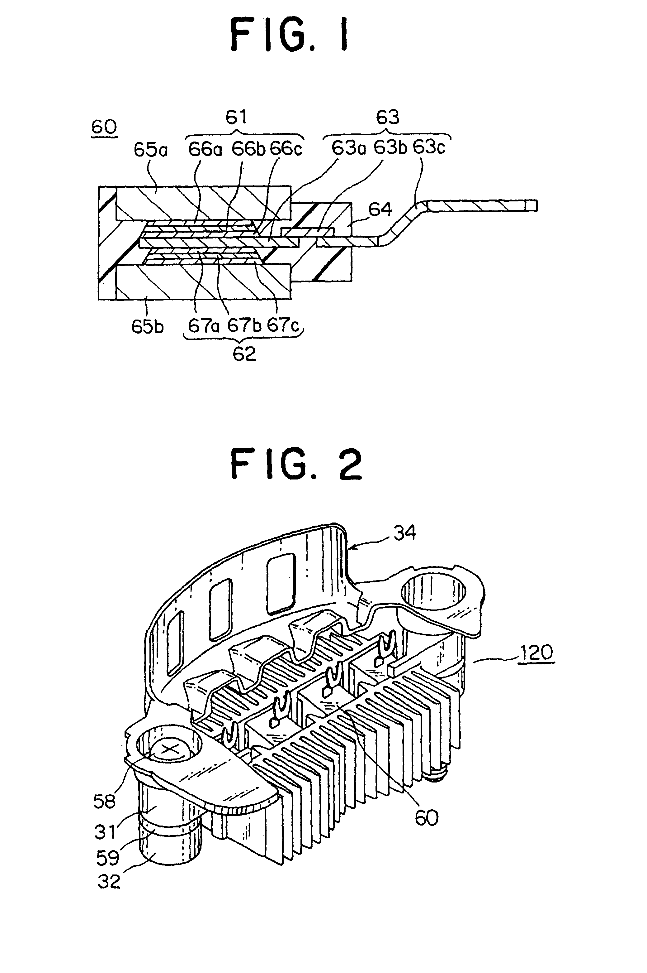
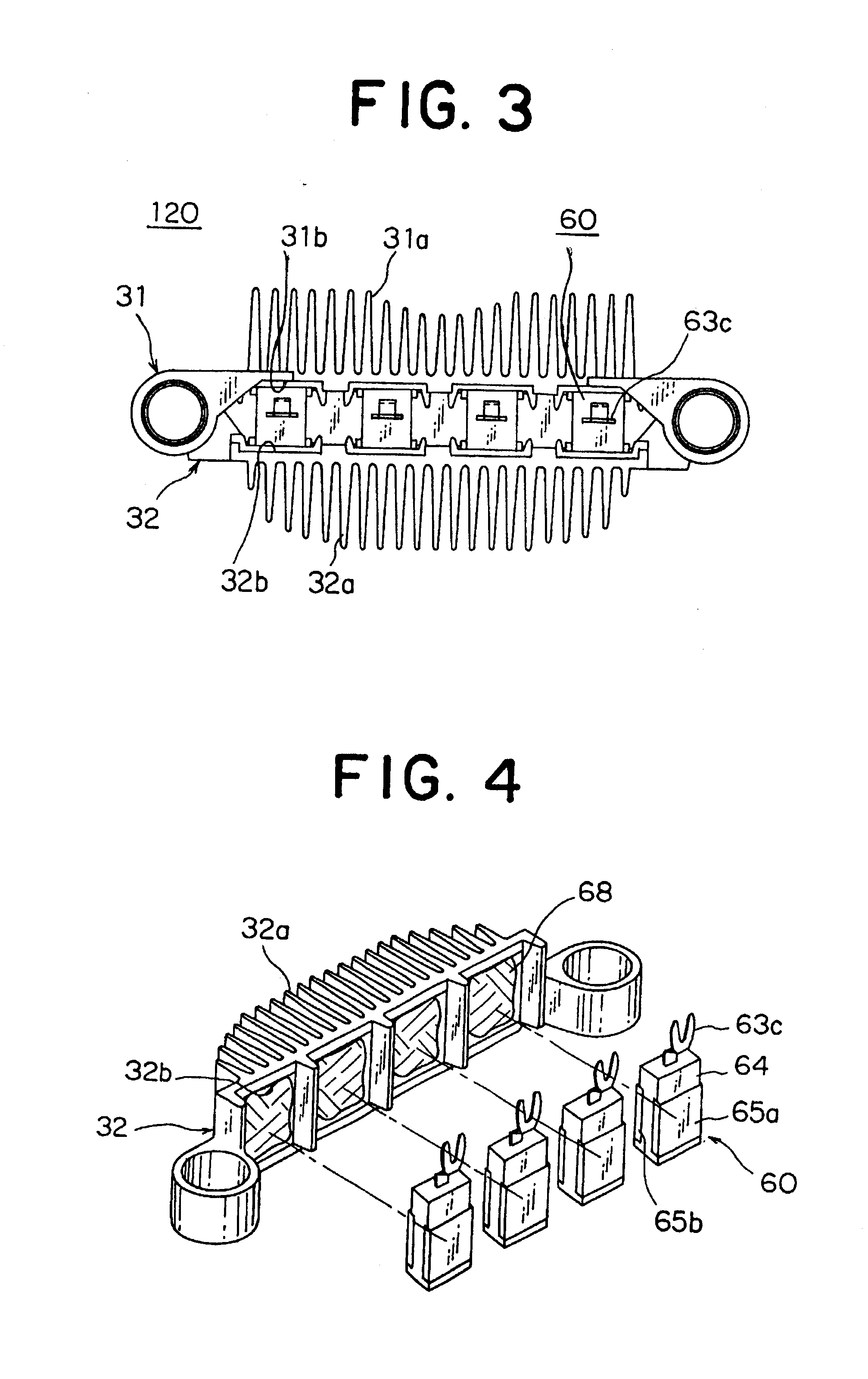
[0093]FIG. 1 is a sectional view showing the structure of a diode package forming a rectifier unit of a vehicle AC generator according to a first embodiment of the present invention; FIG. 2 is a perspective view of the rectifier unit equipped in the vehicle AC generator according to the first embodiment of the present invention; FIG. 3 is a bottom plan view of the rectifier unit equipped in the vehicle AC generator according to the first embodiment of the present invention; FIG. 4 is a perspective view for showing a joining method of the diode package in the rectifier unit equipped in the vehicle AC generator according to the first embodiment of the present invention; FIG. 5 is an assembly view of the rectifier unit equipped in the vehicle AC generator according to the first embodiment of the present invention; FIG. 6 is a perspective view for showing an assembled state of a stator and the rectifier unit according to the first embodiment of the present invention; and FIG. 7 is a cir...

second embodiment

[0121]FIG. 8 is a perspective view for showing a joining method of a diode package in a rectifier unit equipped in a vehicle AC generator according to a second embodiment of the present invention.

[0122]In FIG. 8, a diode package 60A is formed by depositing the unidirectionally conducting elements for the positive- and negative-electrode sides (not shown) in one piece via the tab of the AC input terminal 63, wherein a base 70a for the positive-electrode side is formed to have a disc shape; a base 70b for the negative-electrode side is formed to have a disc shape having a larger diameter than that of the base 70a; and the unidirectionally conducting elements for the positive- and negative-electrode sides, the AC input terminal 63, and the bases 70a and 70b for the positive- and negative-electrode sides are sealed with the insulating resin 64. The insulating resin 64 is formed to have a cylindrical shape having the same diameter as that of the base 70a for the positive-electrode side, ...

third embodiment

[0129]FIG. 9 is a perspective view for showing a joining method of a diode package in a rectifier unit equipped in a vehicle AC generator according to a third embodiment of the present invention.

[0130]In FIG. 9, a base 71a for the positive-electrode side is formed to have a racetrack shape while a base 71b for the negative-electrode side is formed to have a racetrack shape having a larger diameter than that of the base 71a for the positive-electrode side. To form a diode package 60B, four pairs of the unidirectionally conducting elements for the positive- and negative-electrode sides deposited in one piece interposing the tab of the AC input terminal 63 therebetween are aligned between bases 71a and 71b for the positive- and negative-electrode sides and the insulating resin 64 is provided between the bases 71a and 71b for the positive- and negative-electrode sides so as to seal the four pairs of the unidirectionally conducting elements. The insulating resin 64 is formed to have a ra...


PUM


Abstract

A vehicle AC generator having a rectifier unit with cooling plates for the positive-electrode and negative-electrode sides, each having principal planes opposing each other; and a diode package disposed between the cooling plates for the positive-electrode and negative-electrode sides. The diode package has a base for the positive-electrode side formed of a metallic plate and joined to a cathode face of the unidirectionally conducting element for the positive-electrode side; a base for the negative-electrode side formed of a metallic plate and joined to an anode face of the unidirectionally conducting element for the negative-electrode side; and an insulating resin provided so that the unidirectionally conducting elements for the positive-electrode and negative-electrode sides are embedded therein. The end face of the base for the positive-electrode side is joined to the principal plane of the cooling plate for the positive-electrode side while the end face of the base for the negative-electrode side is joined to the principal plane of the cooling plate for the negative-electrode side.

Description

BACKGROUND OF THE INVENTION[0001]1. Field of the Invention[0002]The present invention relates to vehicle AC generators for equipping passenger vehicles and trucks, and in particular relates to a structure of a rectifier unit applied to the vehicle AC generator.[0003]2. Description of the Related Art[0004]FIG. 21 is a sectional view showing a structure of a conventional vehicle AC generator disclosed in Japanese Unexamined Patent Application Publication No. 8-182279, for example; FIG. 22 is a bottom plan view showing a rectifier unit for equipping the conventional vehicle AC generator; FIG. 23 is a schematic representation for showing an assembly procedure of a stator and the rectifier unit in the conventional vehicle AC generator; and FIG. 24 is a circuit diagram showing an example circuit of the conventional vehicle AC generator.[0005]As shown in FIG. 21, the conventional vehicle AC generator is formed so that a Lundell-type rotor 7 is rotatably fitted in a case 3 formed of a front...

Claims


Application Information

Patent Timeline
Patent Type & Authority Patents(United States)
IPC IPC(8): H01L23/433H01L23/34H01L25/11H01L25/10H02K11/04H02K9/06H02K9/28H02K19/22
CPCH01L23/4334H01L24/33H01L25/074H01L25/115H02K11/046H01L23/49562H01L2224/29111H01L2224/32245H01L2924/01002H01L2924/01004H01L2924/01013H01L2924/01029H01L2924/01033H01L2924/01039H01L2924/0105H01L2924/01078H01L2924/01082H01L2924/01006H01L2924/01074H01L2924/01322H01L2924/0132H01L2924/15747H01L2924/12036H01L2924/181H02K11/05H01L2924/00H01L2924/00012H02K19/36
Inventor KASHIHARA, TOSHIAKIKASHIBA, YOSHIHIROMAEKAWA, SHIGEKI
Owner MITSUBISHI ELECTRIC CORP
Why Eureka
Try Eureka