

Remote controller and electrical apparatus controlled by the same
- Summary
- Abstract
- Description
- Claims
- Application Information
AI Technical Summary
Benefits of technology
Problems solved by technology
Method used
Image

Examples
first embodiment
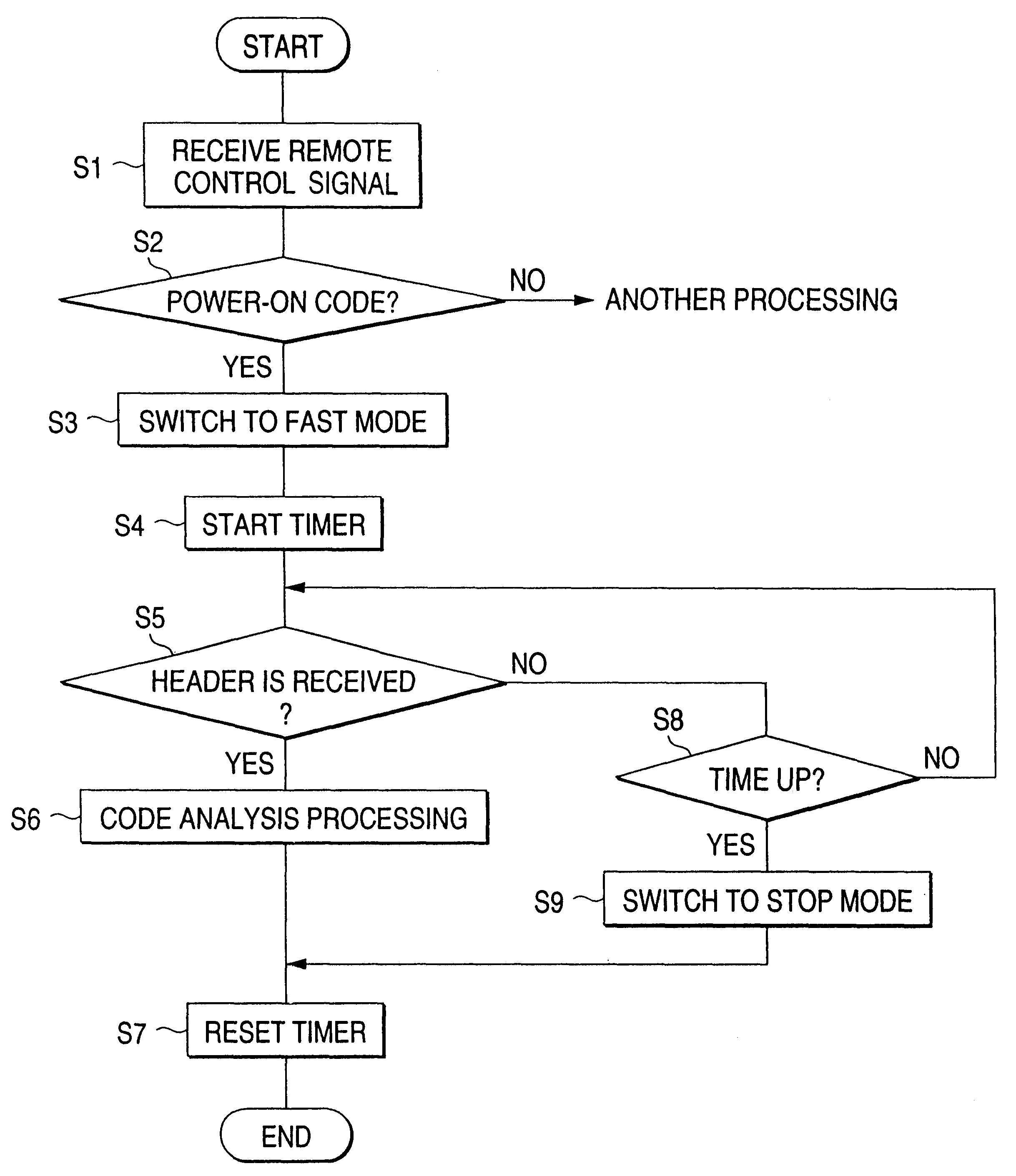
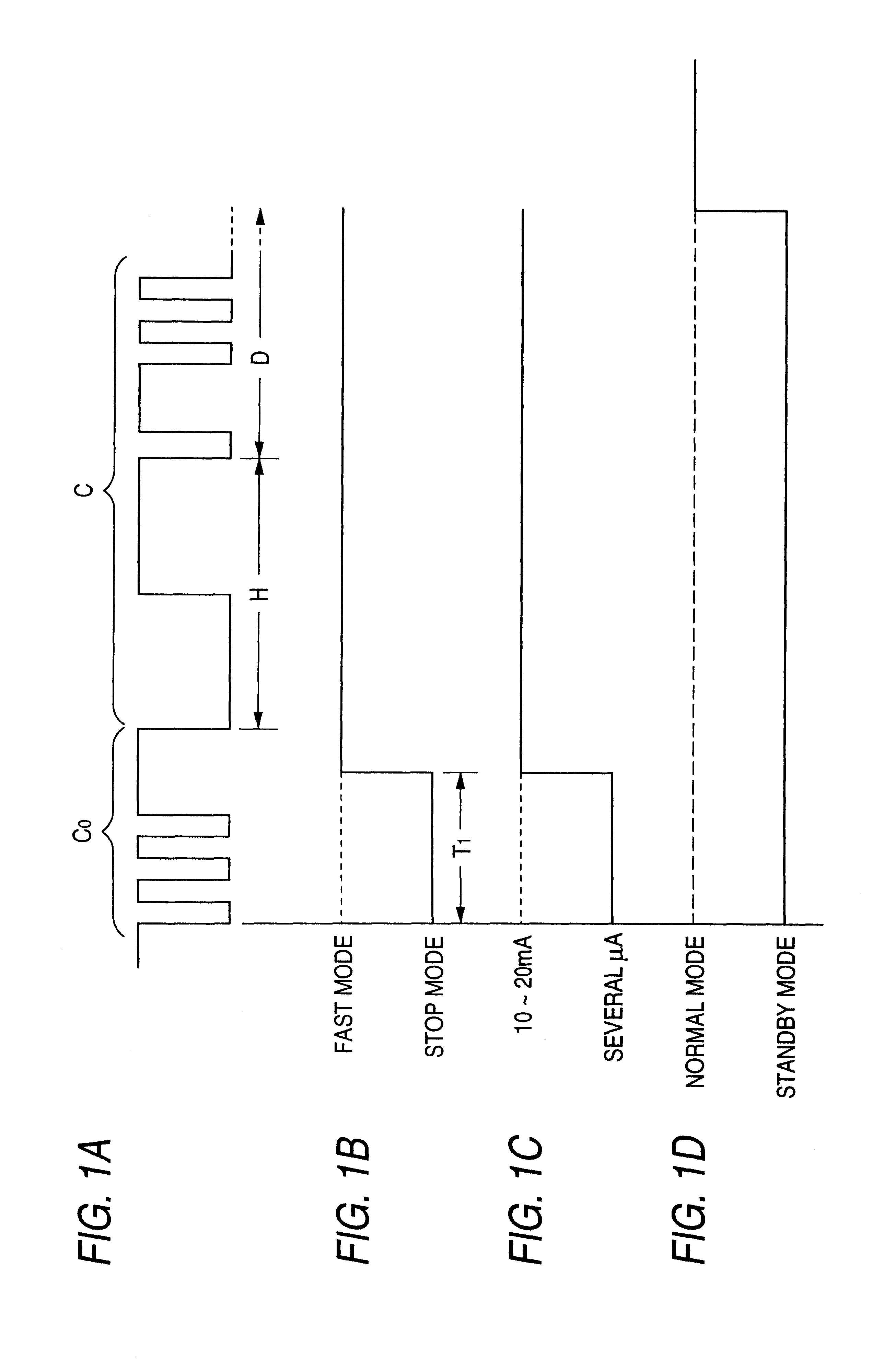
[0021]Hereinafter, the invention will be described. The block diagram of the embodiment of the invention is strictly identical with that of FIG. 3, and hence its detailed description is omitted. The reference numerals of FIG. 3 are used also in the following description. In FIG. 1, A is a waveform chart showing the remote control signal which is transmitted from the remote controller 13. The remote control signal consists of a portion of the code C, and a portion of a code Co preceding the code portion. The code C corresponds to the data code portion in the invention, and the code Co to the power-on code portion in the invention.
[0022]The code C is identical with that of the related art shown in FIG. 5, and configured by the leading header H and the subsequent data signal D. The header H is a code indicating that the signal is a remote control signal, and, in order to be clearly distinguished from noises, the pulse width is set to be long. The data signal D consists of a pulse train...
second embodiment
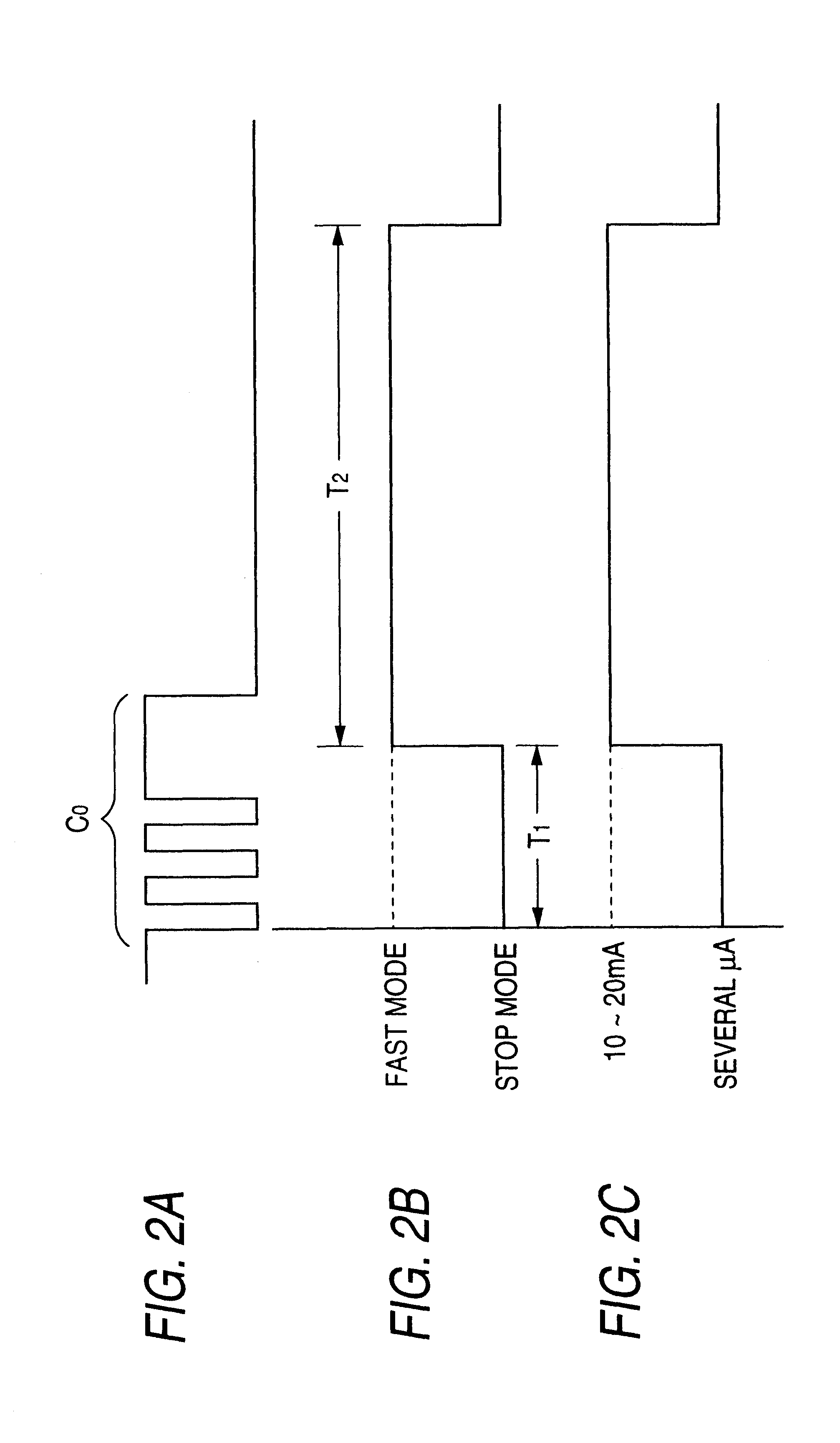
[0033]As a countermeasure against the above, a second embodiment may be contemplated. FIG. 2A is a waveform chart showing a remote control signal which is transmitted from the remote controller 13. FIG. 2B is a waveform chart showing the operation mode of the microcomputer 7. FIG. 2C is a waveform chart showing the current consumed by the microcomputer 7. In the charts, when the signal receiving section 5 fails to receive the header H of the data code portion C within a predetermined time period T2 (for example, 10-15 msec) after the operation mode is switched to the fast mode, the operation mode of the microcomputer 7 is switched from the fast mode to the stop mode.
[0034]According to this configuration, it is possible to prevent the situation in which the operation mode is caused by a noise signal to be kept to the fast mode and the current of the microcomputer 7 is wastefully consumed, from occurring. In the above, the time period T2 elapsed after switching to the fast mode is use...
PUM
 Abstract
Description
Claims
Application Information