Fixing device

a technology of fixing rollers and fixing parts, which is applied in the direction of electromechanical heating, electric/magnetic/electromagnetic heating, instruments, etc., can solve the problems of reducing affecting the efficiency of induction heating, and wasting time, so as to reduce the amount of heat loss, the effect of reducing the thermal capacity of the heating layer and reducing the heat loss

Inactive Publication Date: 2005-04-19
SEIKO EPSON CORP
View PDF24 Cites 20 Cited by
  • Summary
  • Abstract
  • Description
  • Claims
  • Application Information

AI Technical Summary

Benefits of technology

[0096]In the above configurations, a heat loss by the heat transfer from the heating layer of the fixing roller to the bearings and structure members is lessened. Further, the thermal capacity of the heating layer is reduced. A flux density is increased at portions near both ends of the roller where a flux density is low, whereby an amount of heat generated there is increased.
[0097]Accordingly, a time taken for the fixing roller to be heated to a predetermined temperature is reduced. A time from a print start

Problems solved by technology

Therefore, much time is taken till a temperature on the surface of the fixing roller 21 reaches a predetermined level, and the thermal response is not good.
Accordingly, the fixing device suffers from such a problem that an efficiency of the induction heating is reduced.
The structure of it resembles the one mentioned above, and suffers from a similar problem.
Additionally, it is impossible to quantitatively grasp its connection difference.
This necessitates the provision of the resonance inverter for each coil, and hence results in increase of the cost to manufacture.
Accordingly, the magnetic coupling of the coil with the metal sleeve is weak, so that the heating efficiency is small.
Where the core is used, a region from which the magnetic field emanates is limited, and hence the heating by the eddy current is limited in its amount.
This results in ineffective heating of the metal sleeve.
As a result, the release layer is easy to deteriorate.
In other words, the releasing property is poor.
As a result, a frictional force present between

Method used


Image

  • Fixing device
  • Fixing device
  • Fixing device

Examples


first embodiment

[0140]The preferred embodiment of the present invention will be described with reference to the accompanying drawings. the invention will be discussed below.

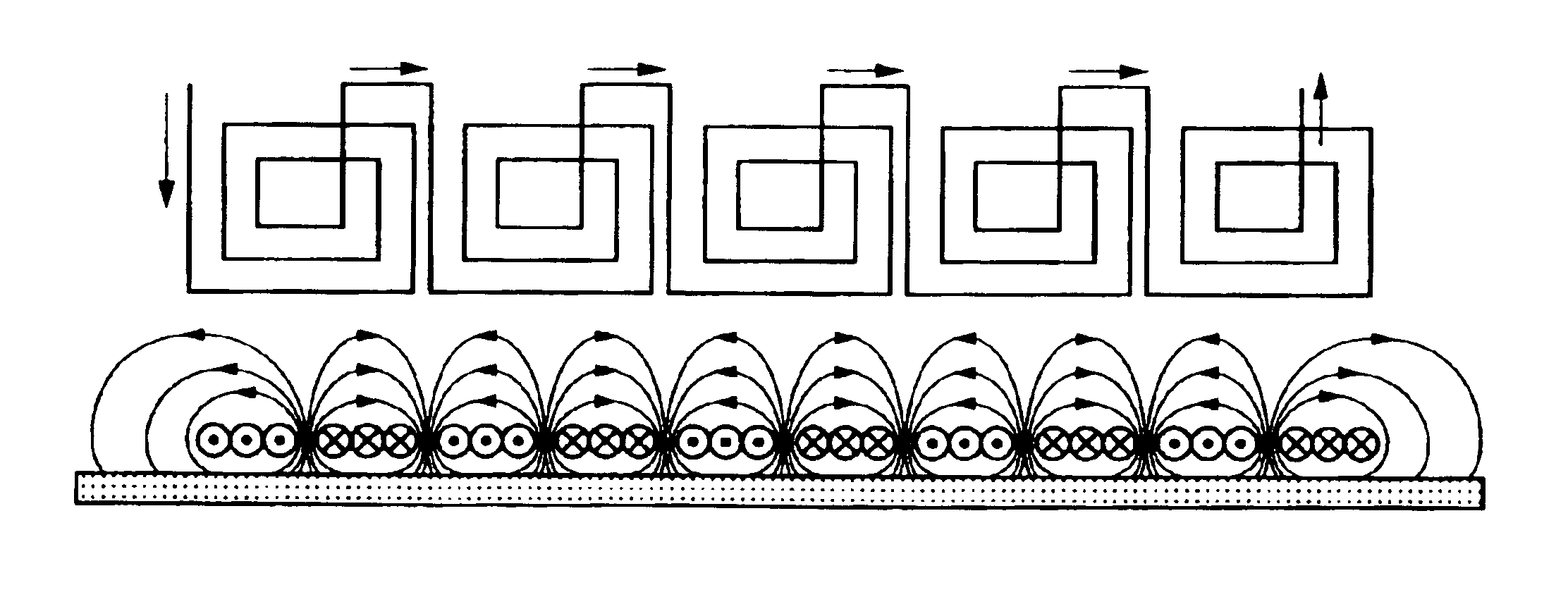
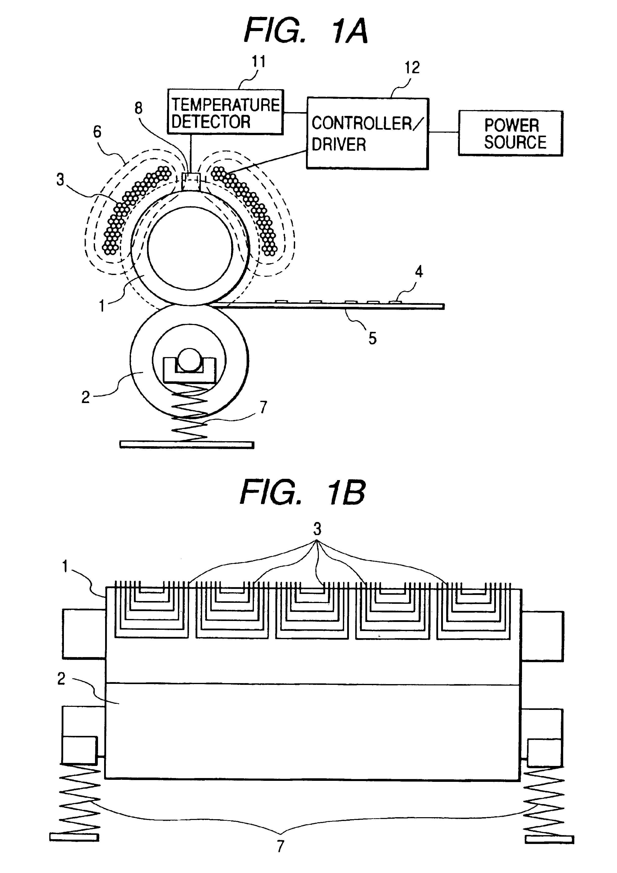
[0141]In FIG. 1A, a fixing roller 1 is formed with a heating layer, which is electrically conductive and small in thermal capacity, and a release layer. If necessary, an elastic layer of several tens to several hundreds μm thick is additionally layered under the release layer. The heating layer must be conductive in order to efficiently generate an eddy current therein by an AC magnetic field developed from a coil 3 (reference numeral 6 denotes a magnetic flux from the coil 3). The release layer is provided to secure an easy separation of fused toner from the fixing roller 1, viz., to prevent an offset of the toner image. A preferable material of the release layer is any of fluorine plastics (PFA, PTFE, PEP), silicone resin, fluororubber, silicone rubber and others. A thickness of the release layer is preferably within several t...

second embodiment

[0164]the present invention will be discussed below.

[0165]In FIG. 8A, a fixing roller 201 includes a core bar which enables the fixing roller to rotate, and is rotatably supported at both ends by means of bearings. A rotational torque from a motor is transmitted to the fixing roller by way of gears and a belt, and in turn is rotated at a fixed angular velocity. An elastic layer for forming a nip is layered on the circumferential outer surface of the core bar. A heating layer and a release layer are further layered on the circumferential outer surface of the elastic layer. A pressure roller 202 is formed with a core bar and an elastic layer. When it is used for both-side printing, a release layer is formed on the surface of the pressure roller. The pressure roller is confronted with the fixing roller 201 and pressed by the spring 207 to form a nip between them, and follows in rotation the fixing roller 201 with a frictional contact therebetween. The detailed structure of the fixing r...

third embodiment

[0195]FIG. 15 shows a fixing device capable of easily forming a horizontal nip, which is the invention. An auxiliary roller pair 209 is in contact with a pair of a fixing roller 201 and a pressure roller 202 at a position located upstream of a pair of a fixing roller 201 and a pressure roller 202, and in this state assists the fixing and pressure rollers in forming a nip therebetween. The auxiliary roller pair 209 may also be designed so as to assist the fixing and pressure rollers in the nip formation in a state that the roller pair is in contact with at least the fixing roller 201.

[0196]It should be understood that the invention is not limited to the above-mentioned embodiments, but may variously be modified, altered and changed within the true spirits of the present invention.

[0197]In the fixing device of the invention, the fixing roller has a structure which includes a thin metal heating layer which reduces its thermal capacity and a rise time of heating, a core bar, an elastic ...


PUM


Abstract

A fixing roller and a pressure roller form a nip therebetween to fix a recorded image onto a recording sheet provided into the nip. A coil provides alternating magnetic field with respect to the fixing roller to inductively heat the fixing roller. The coil includes a plurality of coil segments arranged in an axial direction of the fixing roller. The coil segments are connected in a manner of either forward connection or alternate connection. A controller determines either the forward connection or the alternate connection such that an heating efficiency due to the induction heating has a larger value.

Description

BACKGROUND OF THE INVENTION[0001]The present invention relates to a fixing device of a printer, and more particularly to a fixing device for an electrophotography basis printer. Further, the invention relates to a fixing device for drying a solvent contained in an ink jet printer.[0002]There are known a fixing device which uses a halogen lamp for its heating source, and a fixing device which uses an electromagnetic induction heater for a heat source. In the related fixing device using a halogen lamp for its heating source, as shown in FIG. 29, a halogen lamp 23 cylindrical in shape is located within a fixing roller 21 hollowed, while being centered. The halogen lamp 23, when fed with current, emits an electromagnetic wave containing mainly infrared rays, and it reaches the inside of the fixing roller 21. It is converted into heat in the roller. The heat is transferred to the outside of the fixing roller 21. A recording sheet 25 bearing a marking material (toner image 24) is heated a...

Claims


Application Information

Patent Timeline
IPC IPC(8): G03G15/20
CPCG03G15/2053G03G15/2042
Inventor SAKAGAMI, YUSUKE
Owner SEIKO EPSON CORP
Why Eureka
Try Eureka