Oscillator and communication apparatus

Inactive Publication Date: 2005-04-19
SEIKO EPSON CORP
View PDF9 Cites 14 Cited by
  • Summary
  • Abstract
  • Description
  • Claims
  • Application Information

AI Technical Summary

Benefits of technology

[0028]Since the oscillator allows adjustment of a frequency-temperature characteristic of the output signal in accordance with an intended use thereof as described above, hi

Problems solved by technology

However, since TCXOs, VCXOs, etc. have generally been developed independently of each other, and e

Method used


Image

  • Oscillator and communication apparatus
  • Oscillator and communication apparatus
  • Oscillator and communication apparatus

Examples


first embodiment

[1] First Embodiment

[1-1] Overall Construction of the First Embodiment

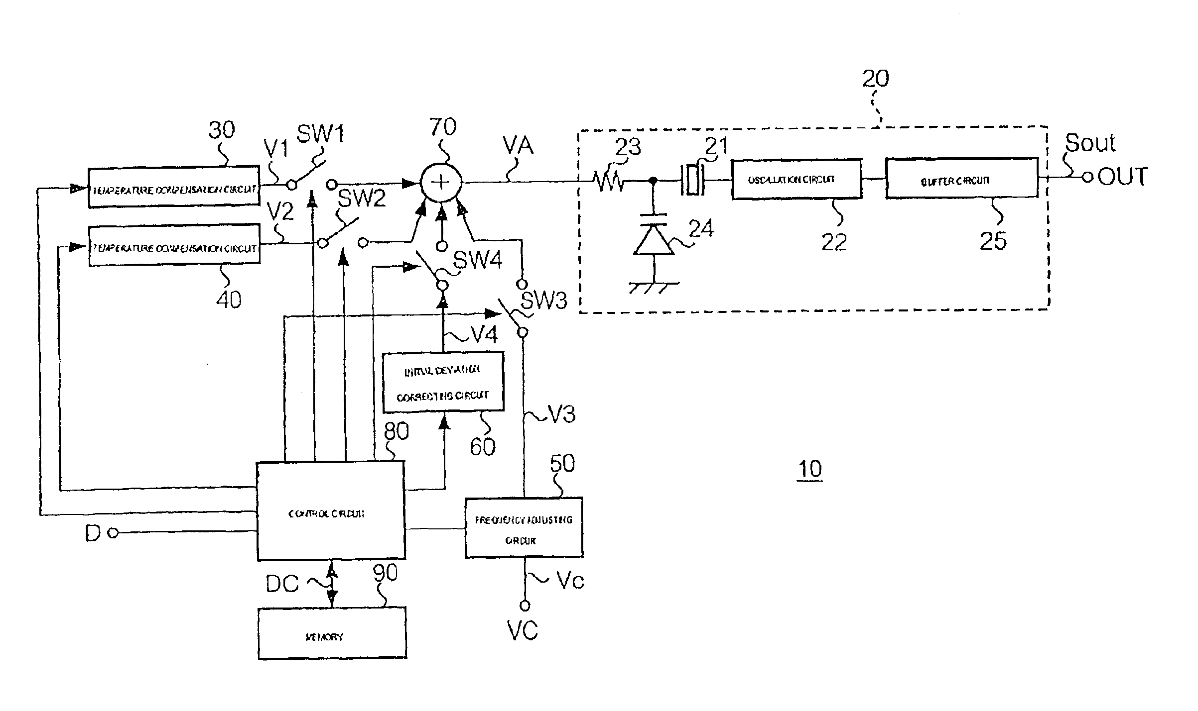
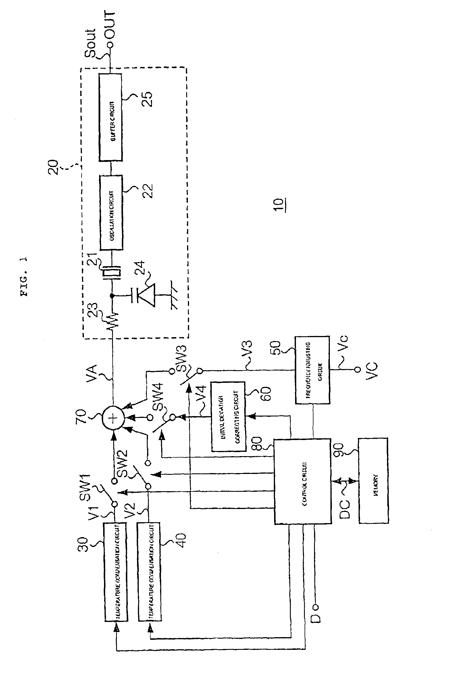
[0051]FIG. 1 is a principle construction diagram of an oscillator according to a first embodiment of the present invention.

[0052]The oscillator 10 includes a voltage-controlled oscillation circuit 20, temperature compensation circuits 30 and 40, a frequency adjusting circuit 50, an initial deviation correcting circuit 60, an addition circuit 70, a control circuit 80, a memory 90, and switches SW1, SW2, SW3, and SW4.

[0053]The voltage-controlled oscillation circuit 20 includes an oscillation circuit 22 for causing oscillation of a piezoelectric vibrator 21 such as a crystal vibrator or a ceramic vibrator; a variable-capacitance diode (hereinafter referred to as a varicap) 24 connected to a midpoint node between an input resistor 23 and the piezoelectric vibrator 21; and a buffer circuit 25. The frequency of an oscillation signal Sout output from an output terminal OUT changes in accordance with the capacitance of th...

second embodiment

[2] Second Embodiment

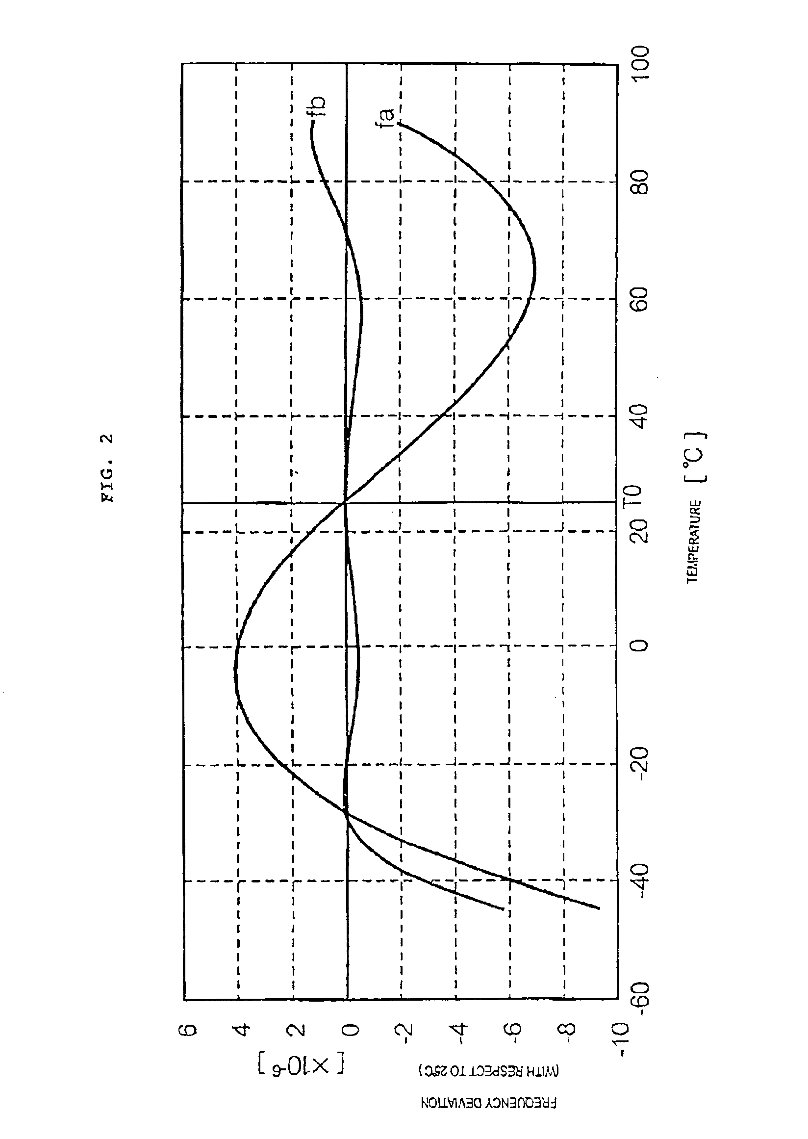
[0089]An oscillator 10 according to the second embodiment differs from the oscillator 10 according to the first embodiment in that the temperature compensation circuit 30 outputs the temperature compensation voltage V1 only in a temperature range in which the temperature compensation voltage V2 of the temperature compensation circuit 40 does not suffice to keep the oscillation signal Sout within a predetermined range of frequency deviation. More specifically, as shown in FIG. 13, the temperature compensation voltage V1 of the temperature compensation circuit 30 is supplied to the voltage-controlled oscillation circuit 20 via the addition circuit 70 only in temperature ranges of Ta to Tb and Tc to Td in which a frequency-temperature characteristic fc of the oscillation signal Sout that has been temperature-compensated by the temperature compensation circuit 40 is not within an intended range of frequency deviation. Accordingly, a frequency-temperature characteris...

third embodiment

[3] Third Embodiment

[0090]FIG. 14 is a principle construction diagram of an oscillator according to a third embodiment.

[0091]The oscillator 10 according to the third embodiment significantly differs from the oscillators 10 according to the embodiments described above in that an initial deviation correcting circuit 60A is connected to the anode of the varicap 24 of the voltage-controlled oscillation circuit 20 via the switch SW4. In accordance therewith, a midpoint node between the anode of the varicap 24 and the switch SW4 is grounded via a bias resistor Rx.

[0092]FIG. 15 is a circuit diagram showing the initial deviation correcting circuit 60A together with components in the vicinity thereof.

[0093]The initial deviation correcting circuit 60A includes a base capacitor C0 that functions as a fixed-connection capacitor, one end thereof being connected to the switch SW4 and the other end thereof being grounded; L capacitors Cj (j=1 to L) that function as capacitors to be selected for ch...


PUM


Abstract

An oscillator 10 includes temperature compensation circuits 30 and 40, a frequency adjusting circuit 50, and an initial deviation correcting circuit 60. Switches SW 1 to 4 are controlled based on control data DC stored in a memory 90 so that a temperature compensation voltage V1, a temperature compensation voltage V2, a frequency adjusting voltage V3, and an initial deviation correcting voltage V4, output from the above circuits, are selectively added, supplying a sum to a voltage-controlled oscillation circuit 20 as a control voltage VA.

Description

TECHNICAL FIELD[0001]The present invention relates to oscillators used in communication apparatuses such as cellular phones, and communication apparatuses incorporating the oscillators. More specifically, it relates to an oscillator that allows changing functions and a communication apparatus incorporating the oscillator.BACKGROUND ART[0002]In general, crystal oscillators are classified, by their functions, as SPXOs (Simple Packaged Crystal Oscillators), VCXO (Voltage Controlled Crystal Oscillators), TCXO (Temperature Compensated Crystal Oscillators), etc. An SPXO is a crystal oscillator that does not perform temperature compensation. A TCXO (temperature-compensated oscillator) is a crystal oscillator that performs temperature compensation so as not to change output frequency even if ambient temperature changes. A VCXO (voltage-controlled oscillator) is a crystal oscillator that changes output frequency in accordance with a control voltage that is supplied externally. A crystal osci...

Claims


Application Information

Patent Timeline
IPC IPC(8): H03L1/02H03L1/00H03B5/32H03B1/00
CPCH03B5/32H03L1/025H03B2201/0208
Inventor OKA, MANABUICHINOSE, KAZUSHIGE
Owner SEIKO EPSON CORP
Why Eureka
Try Eureka