

Floor-to-ceiling wall panel system
- Summary
- Abstract
- Description
- Claims
- Application Information
AI Technical Summary
Benefits of technology
Problems solved by technology
Method used
Image

Examples
first embodiment
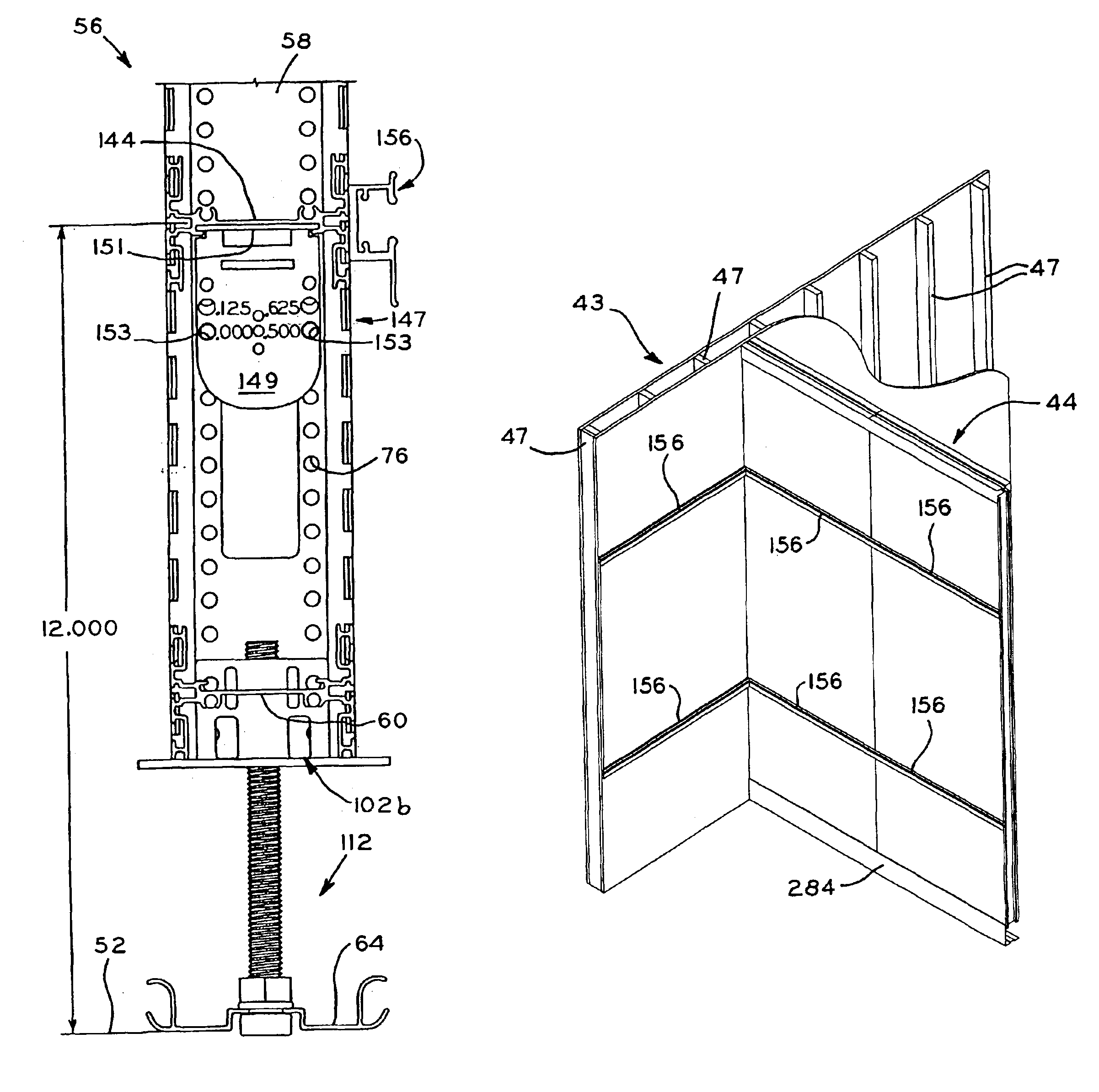
[0123]Referring to FIGS. 5A, 5B, 6A, and 6B, corner blocks 62a are shown. Corner blocks 62a generally include block portion 106 with plate 100a attached thereto. Block portion 106 and plate 100a may be an integral zinc, die-cast part. Corner blocks 62a include first bore 108 therein, which is threaded along at least a portion thereof, and a pair of second bores 110 disposed on each side of first bore 108, wherein each of the foregoing are aligned with corresponding apertures in plate 100a. Alternatively, block portion 106 and plate 101a of corner blocks 62a may be unitarily formed, of a high strength, injection-molded plastic, in which first and second bores 108, 110 may include threaded or smooth steel insert sleeves (not shown) therein.
second embodiment
[0124]Referring to FIGS. 5C through 5E and 6C through 6E, corner blocks 62b are shown, which are similar to corner blocks 62a, wherein the same reference numerals will be used to refer to common parts between corner blocks 62a and 62b. Corner locks 62b are formed of a single, integral piece of a hard plastic material, and include block portion 106 and plate portion 100b. Each plate portion 100b includes cam slot 101 and a pair of half cam slots 103, with cam slot 101 including wide portion 105 tapering to narrow portion 107. One of the half cam slots 103 in plate portion 100b includes a wide portion 105 and the other of the half cam slots 103 in plate portion 100b includes a narrow portion 107. The function of cam slots 101 and half cam slots 103 will be explained below.
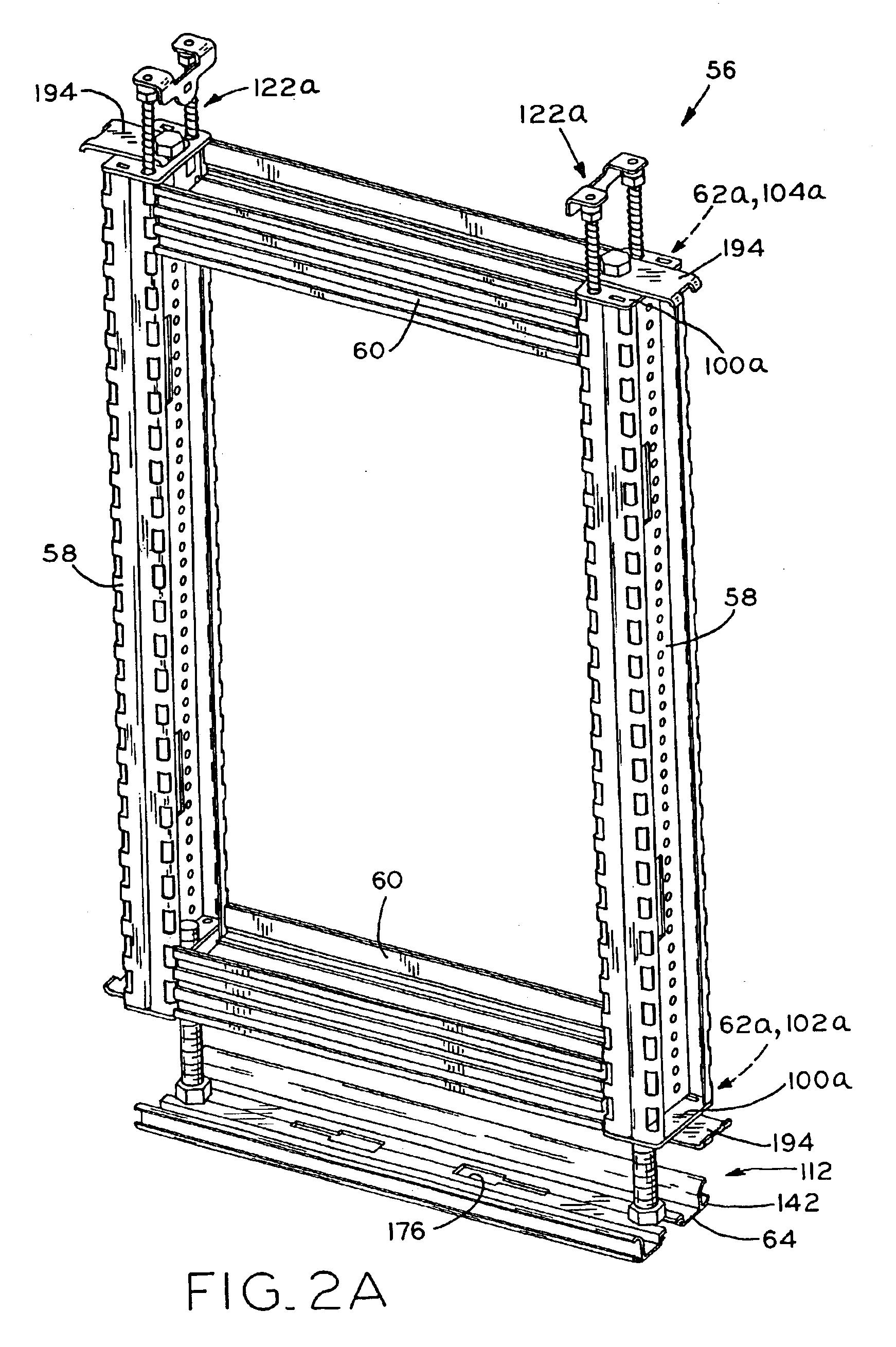
[0125]Panel support blocks 102a, 102b according to first and second embodiments are shown in FIGS. 6A through 6E, and each include vertical adjustment assembly 112 for vertically adjustable connecting panel frame 56...
PUM
 Abstract
Description
Claims
Application Information